
Note:
- Wash all parts before installation.
- Always use new cylinder head gaskets and exhaust and intake manifold gaskets.
- Always use new cylinder head bolts.
- The cylinder head gasket is metal, so be careful not to bend it before installing it.
- Turn the crankshaft clockwise to set the piston of the first cylinder to the top dead center (TDC) position.
1. Install the oil control valve filter.
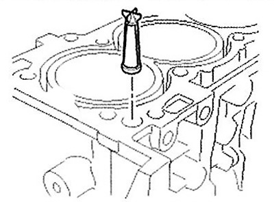
Attention: Keep the filter clean.
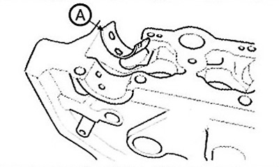
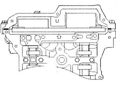
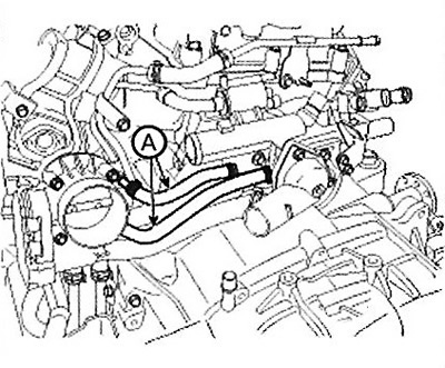
2. Install the cylinder head gasket (A) to the cylinder block.
Note:
- Please pay attention to the installation order.
- Apply sealant (Loctite 5900H) to the marked areas (B).
- After applying the sealant, the cylinder head must be installed within 5 minutes.
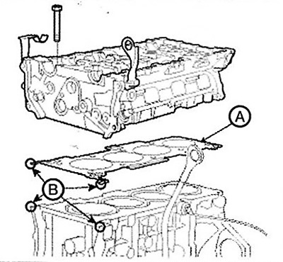
3. Install the cylinder head carefully to avoid damaging the gasket.
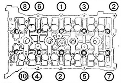
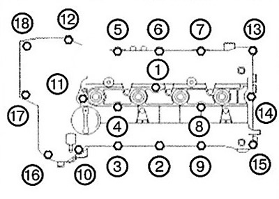
4. Screw in the cylinder head bolts.
Apply a thin layer of engine oil to the threaded parts and under the heads of the cylinder head bolts.
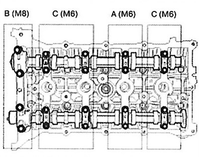
Using a hex key, tighten the 10 cylinder head bolts and washers in the order shown in the illustration.
Note: Tightening torque: 32.4-36.3 Nm + 90-95° + 90-95°.
5. Install the valve (A) to control the oil supply to the inlet valves.
Note: Tightening torque: 9.8 - 11.8 Nm.
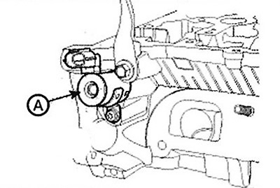
6. Install the valve (A) to control the oil supply to the outlet valves.
Note: Tightening torque: 9.8- 11.8 Nm.
Attention.
- Do not damage or drop the oil control valves.
- Keep the filter clean.
- When the oil control valves are installed on the engine, do not start the engine while holding the valve bracket.
7. Install the camshafts.
Note: Apply a thin layer of engine oil to the camshaft bearings.
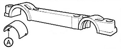
Install the lower exhaust camshaft bearing shell (A).
Install the camshafts (A).
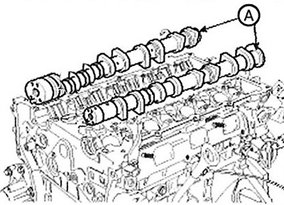
Install the exhaust camshaft upper bearing shell (A).
Install the bearing caps in their original position.
Tightening order: group A—> group B -> group C. Tightening torque: step 1: M6: 5.9 Nm, M8: 14.7 Nm, step 2: M6: 10.8 - 12.7 Nm, M8: 27.5 - 31.4 Nm.
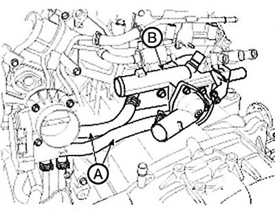
8. Install the coolant outlet block assembly (A).
Note:
Tightening torque:
- Bolts: 14.7 - 19.6 Nm.
- Nuts: 18.6-23.5 Nm.
Attention.
- First install the coolant outlet block assembly and water inlet hose to the water pump, then tighten the inlet hose nuts.
- Always use new O-rings.
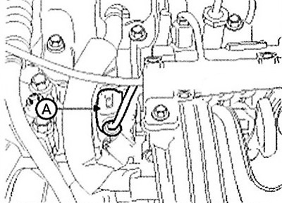
9. Screw in the bolt (A) securing the water inlet pipe.
Note: Tightening torque: 9.8- 11.8 Nm.
10. Install the timing chain.
11. Check the valve clearance.
12. Install the cylinder head cover.
The hardened sealant located on the top surface between the chain cover and the cylinder head must be removed before installing the cylinder head cover.
After applying LOCTITE 5900H sealant, assembly must be completed within 5 minutes.
Note: Thickness of sealant strip: 2.5 mm.
Do not start the engine or perform pressure testing for 30 minutes.
Install the cylinder head mounting bolts as follows:
Tightening torque: step 1: 3.9-5.9 Nm, step 2: 7.8-9.8 Nm.
Caution: Do not reuse the cylinder head gasket.
13. Install the intake and exhaust manifolds.
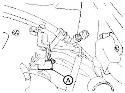
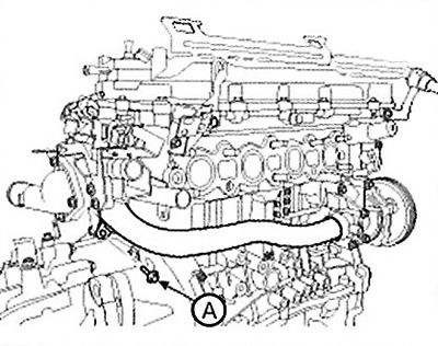
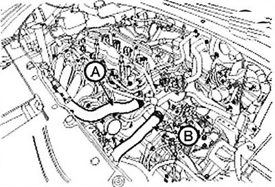
14. Connect the cooling system hoses (A) to the throttle body.
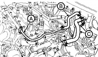
15. Connect the fuel hose (A), brake booster vacuum hose (B) and heater hoses (C).
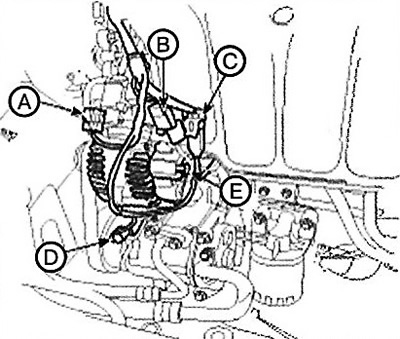
16. Connect the wiring connectors and harness clamps.
(1) Oil control valve (OCV) connector (A).
(2) Connector (A) of the variable intake manifold geometry system (VIS).
(3) Oil pressure sensor (B) connector.
(4) Knock sensor connector (C).
(5) Connector (D) of the air conditioning compressor switch.
(6) Generator connector (E).
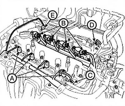
(7) Connectors (A) of injectors.
(8) Ignition coil connectors (B).
(9) Connector (C) of the intake camshaft position sensor.
(10) Connector (D) of the exhaust camshaft position sensor.
(11) Connector (E) of the exhaust valve oil supply control valve.
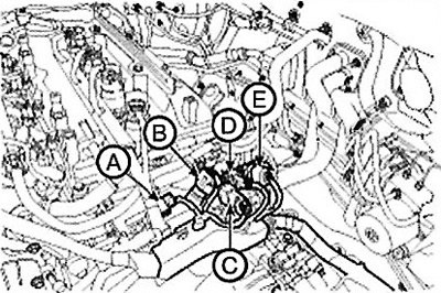
(12) Connector (A) of the electronic throttle control (ETC) system.
(13) Connectors (B) for the manifold absolute pressure (MAP) sensor and the intake air temperature sensor (IATS).
(14) Connector (A) of the purge control solenoid valve (PCSV).
(15) Connector (B) of the coolant temperature sensor (ECTS).
(16) Capacitor connector (C).
(17) Connector (D) of the crankshaft position sensor.
(18) Oxygen sensor connector (E).
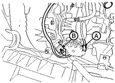
17. Connect the upper (A) and lower (B) radiator hoses.
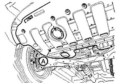
18. Install the engine protection (A).
Note: Tightening torque: 19.6-24.5 Nm.
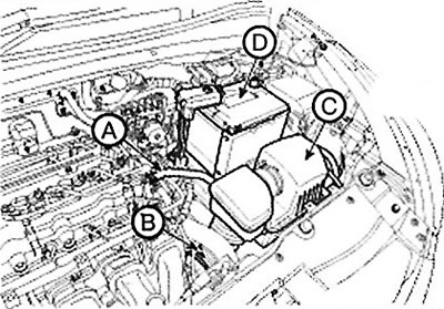
19. Install the battery (D) and connect the positive terminal.
Note:
Tightening torque:
- Positive terminal: 7.8-11.8 Nm.
- Bracket bolt: 9.8-11.8 Nm.
20. Install the air cleaner (C) assembly, then connect the air inlet hose (B) and breather hose (A).
Note:
Tightening torque:
- Hose clamp bolt: 2.9-4.9 Nm.
- Air filter mounting bolts: 7.8-11.8 Nm.
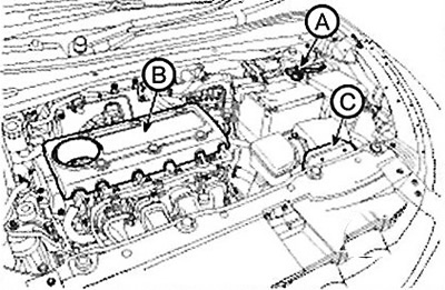
21. Install the air duct (C).
22. Install the engine cover (B).
23. Connect the negative cable (A) to the battery.
Note: Tightening torque: 4.0-6.0 Nm.
24. Perform the following actions:
Fill with engine oil.
Before connecting the wires, clean their clamps and battery terminals with sandpaper. To prevent corrosion, coat the connected clamps with grease.
Check for fuel leaks.
After installing the fuel line, turn the ignition key (do not turn on the starter) so that the fuel pump can operate for about 2 seconds and pressure is generated in the fuel line. Repeat this operation 2-3 times and check the entire fuel line for leaks.
Fill the radiator and reservoir with coolant.
Bleed the cooling system.
Start the engine and let it warm up (until the radiator fan comes on 3-4 times).
Turn off the engine and let it cool. Check the coolant level and top up if necessary. This will remove air from the cooling system.
Replace the radiator cap securely, start the engine again and check for leaks.