
Contents: Cylinder head ⇓ Valves, tappets, guides and valve…⇓ Camshaft ⇓ Exhaust camshaft bearing ⇓ Valve timing mechanism assembly…⇓
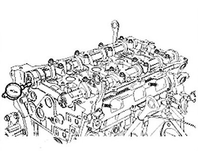
Cylinder head
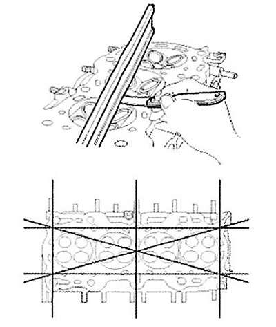
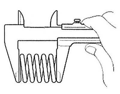
1. Check the non-flatness of the surface of the cylinder head-to-block joint. To do this, use a special ruler and a set of feeler gauges. Placing the ruler in the planes shown in the figure, measure the non-flatness of the joint surface with feeler gauges.
Note: Standard value of surface non-flatness: less than 0.05mm.
2. Check the combustion chambers, intake and exhaust ports and the joint surface with the cylinder block for damage. If any defects are found, replace the cylinder head assembly.
Valves, tappets, guides and valve springs
1. Check the technical condition of the guide bushings and valves.
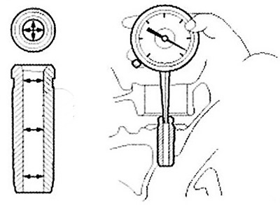
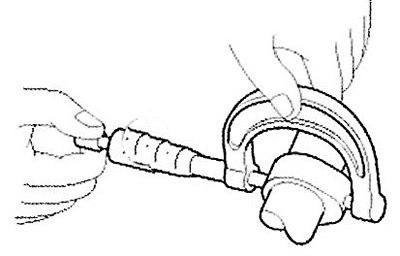
Using a bore gauge, measure the inside diameter of the valve guide as shown in the illustration.
Note: Standard inner diameter: 5.500-5.512mm
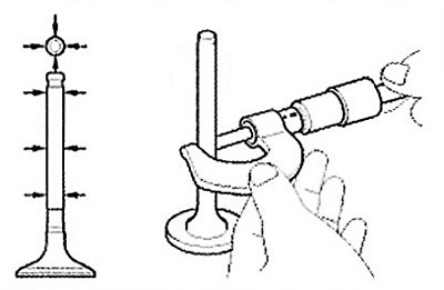
Using a micrometer, measure the outside diameter of the valve stem as shown in the illustration.
Note: Standard valve outer diameter: 5.465~5.480mm (inlet), 5.458~5.470mm (outlet).
The difference between the inside diameter of the guide bushing and the outside diameter of the valve stem is the valve-to-guide clearance.
Note:
Default value:
- Inlet: 0.020 - 0.047 mm.
- Outlet: 0.030 - 0.054 mm.
Maximum permissible value:
- Inlet: 0.07 mm.
- Outlet: 0.09 mm.
If the clearance value is greater than the maximum permissible value, it is necessary to replace the valve assembly with the sleeve.
2. Check the technical condition of the valves.
Check the sharpening angle of the working chamfer of the valve head.
Check the valve surface for excessive wear. If any defects are found, replace the valve with a new one.
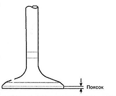
Check the thickness of the valve head band. If the thickness of the valve head band is less than the maximum allowable, the valve must be replaced with a new one.
Note: Standard belt thickness: 1.02 (inlet), 1.09 (outlet).
Measure the overall length of the valve.
Note:
- Standard valve length: 113.18 mm (inlet), 105.84 mm (outlet).
- Maximum permissible valve length: 112.93 mm (inlet), 105.59 mm (outlet).
3. Check the technical condition of the valve seats.
Check that the valve fits tightly to the seat, along its entire circumference. If necessary, replace the valve seats,
Before restoring the valve seats, it is necessary to check the technical condition of the valve guide bushings. If any defects are found, it is necessary to replace the bushing and then restore the seat. The thickness of the working surface of the seat contact with the valve must correspond to the standard value.
4. Check the technical condition of the valve springs.
Using a steel square, measure the amount of deviation from the vertical axis of the spring.
Note:
- Permissible deviation from the vertical axis: 1.5°.
- Maximum permissible deviation: 3°.
Using a caliper, measure the free length of the spring.
Note: Standard spring length is 47.44mm.
Note: If the free length of the spring does not correspond to the standard value, it is necessary to replace the spring with a new one.
5. Using a micrometer, measure the outside diameter of the tappet.
Note: Standard value: 31.964 - 31.980 mm.
6. Using a compass, measure the inside diameter of the tappet hole in the cylinder head.
Note: Inner hole diameter: 32.000 - 32.025mm.
7. Subtract the outside diameter measurement from the tappet inside diameter measurement to determine the clearance.
Note:
- Standard value: 0.020 - 0.061 mm.
- Limit value: 0.07 mm.
Camshaft
1. Using a micrometer, measure the height of the camshaft lobes.
Note: Standard cam lobe height: 44.10 - 44.30 mm (intake), 44.90 - 45.10 mm (exhaust).
Note: If the camshaft lobe height is less than the minimum allowable value, the camshaft assembly must be replaced.
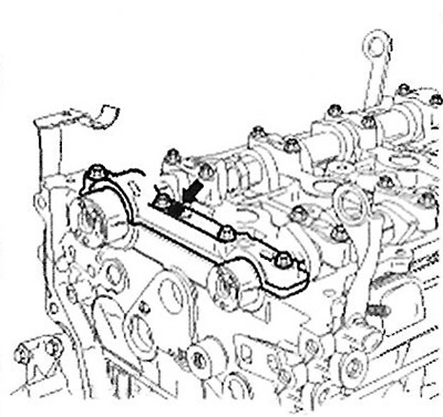
2. Check the clearance in the camshaft bearings.
Clean and wash the bearing caps and camshaft journals.
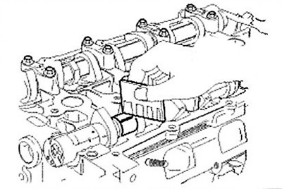
Install the camshafts into the cylinder head.
Place special plastic gauges on the camshaft journals as shown in the figure.
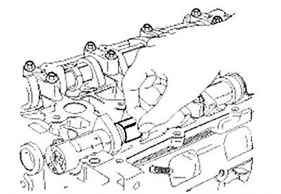
Install the camshaft bearing caps.
Caution: Do not turn the camshaft.
Remove the camshaft bearing caps.
Measure the thickness of the plastic gauge (a scale is included with the plastic gauge kit). From this, determine the amount of clearance in the bearings.
Note:
- Standard clearance value for bearing liner No.1: 0.022 - 0.057 mm, No.2, 3, 4, 5: 0.045 - 0.082 (inlet), No.1: 0 -0.032 mm, No.2,3,4,5: 0.045 - 0.082 (outlet).
- Maximum allowable: No.1: 0.09 mm, No.2,3,4,5: 0.12 mm (inlet); 0.12 (release).
Note: If the bearing clearance exceeds the permissible limit, the camshaft must be replaced. If necessary, replace the bearing caps or the cylinder head assembly.
Remove the plastic gauges completely.
Remove the camshafts.
3. Measure the axial clearance of the camshaft.
Install the camshafts.
Using a dial indicator, measure the end clearance by moving the camshaft forward/backward.
Note:
- Standard camshaft end clearance: 0.04~0.16mm.
- Maximum permissible value: 0.20 mm.
If the axial clearance exceeds the maximum permissible value, the camshaft must be replaced. If necessary, replace the camshaft bearing caps and the cylinder head assembly.
Remove the camshafts.
Exhaust camshaft bearing
1. Check the cylinder head hole mark.
Label location:
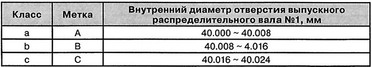
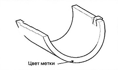
2. Select the bearing class same as the cylinder head as shown in the table.
Label location:
 |
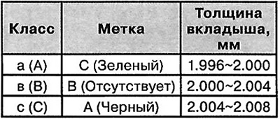 |
Note: Oil clearance: 0 - 0.032 mm.
Valve timing mechanism assembly (phase shifter)
1. Check the technical condition of the variable valve timing mechanism assembly.
Check and make sure that the mechanism does not rotate.
Wrap vinyl tape around all parts of the mechanism except the one shown in the picture below.
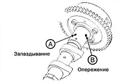
Inlet
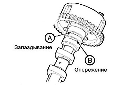
Release
Wrap a special air gun, then apply 150 kPa pressure to the hole on the camshaft (while performing this operation, remove the lock pin).
Note: After spraying engine oil, wipe the surfaces with a rag.
During the above operation, turn the phase shifter assembly in the advance direction by hand (the direction is indicated by an arrow in the figure). When compressed air is supplied, the phase shifter should be moved in the advance direction without force, by hand, except for the position when the locking pin reaches the maximum deviation in the retard direction.
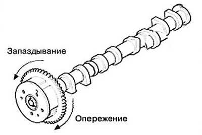
After this, turn the phase shifter back. Check the smoothness of its movement, eliminating jamming.
Note: The range of movement of the phase shifter is 22.5° (inlet), 20° (outlet).
Turn the phase shifter assembly by hand and fix it in the maximum lag position.