
Contents: Connecting rods and crankshaft ⇓ Cylinder block ⇓ Pistons and piston rings ⇓ Piston pins ⇓
Connecting rods and crankshaft
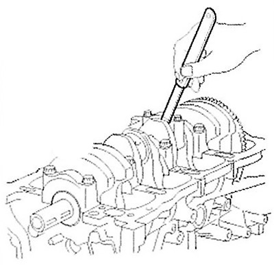
1. Check the connecting rod end clearance. Using a set of feeler gauges, measure the end clearance by moving the connecting rod forward/backward.
Note:
- Standard gap size: 0.1 - 0.25 mm.
- Maximum permissible value: 0.35 mm.
Note:
- If the axial clearance of the connecting rod exceeds the maximum permissible value, it must be replaced with a new one.
- If after installing a new connecting rod the axial clearance exceeds the maximum permissible value, it is necessary to replace the crankshaft assembly.
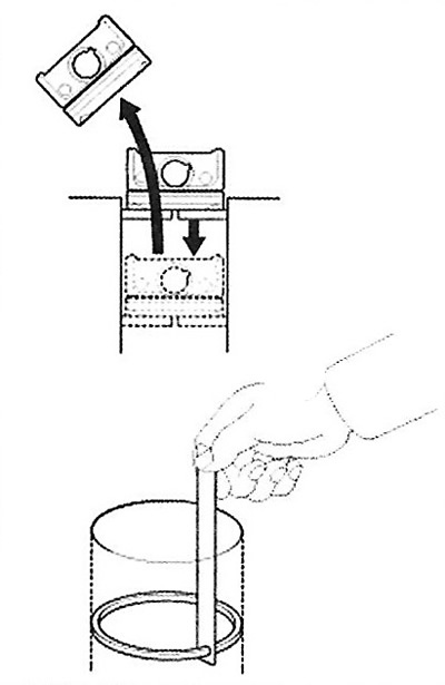
2. Measure the clearance in the connecting rod bearings.
Place alignment marks on the connecting rod and connecting rod cap for proper installation.
Remove the two connecting rod cover mounting bolts.
Remove the connecting rod cap together with the bearing shell.
Clean and wash the bearing and connecting rod journal of the crankshaft.
Place a special plastic gauge on the connecting rod journal along the crankshaft axis.
Install the connecting rod cover and tighten the mounting bolts to a tightening torque of (17.7 - 21.6 Nm) + an additional 88-92°.
Caution: Do not turn the crankshaft.
Loosen the mounting bolts and remove the connecting rod cover.
Measure the thickness of the plastic gauge (the scale is included with the kit).
Note: Standard bearing clearance is 0.031-0.045 mm.
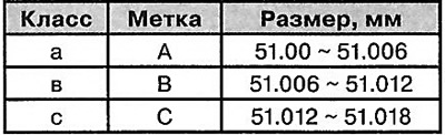
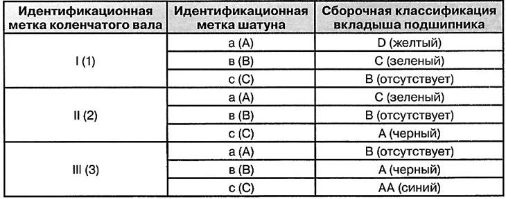
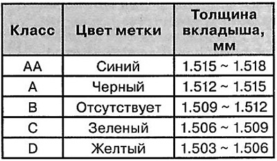
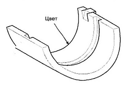
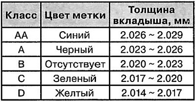
If the plastic gauge is too wide or too thin after removal, the upper bearing shell must be removed and a new one installed. Then repeat the bearing clearance measurement. The shell must be selected according to the marking color (see table below).
Caution: Do not place a washer or scratch the surface of the bearing to adjust the clearance.
If the bearing clearance is still too large or too small, the next bearing shell must be installed and the measurement repeated.
Note: If the bearing clearance cannot be adjusted by selecting liners, the crankshaft assembly must be replaced and the adjustment repeated.
Attention.
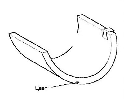
- If the identification mark on the liner is not visible due to carbon deposits, it is necessary to wash it in a solvent. It is prohibited to clean the liner with a scraper or a metal brush.
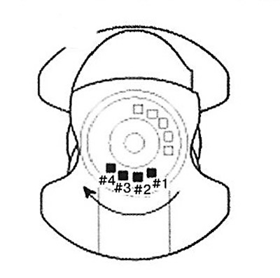
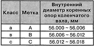
- The location of the connecting rod identification mark is shown below.
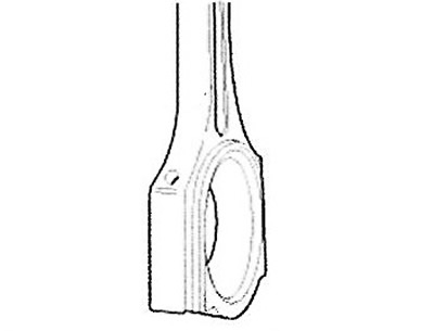
Connecting rod dimensions
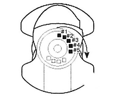
Location of the crankshaft identification mark.
Note: Read the order of the marks according to the arrow in the figure below.
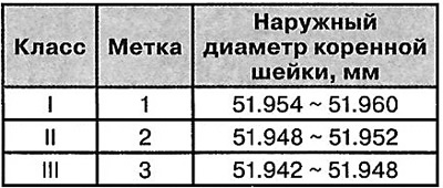
Crankshaft dimensions
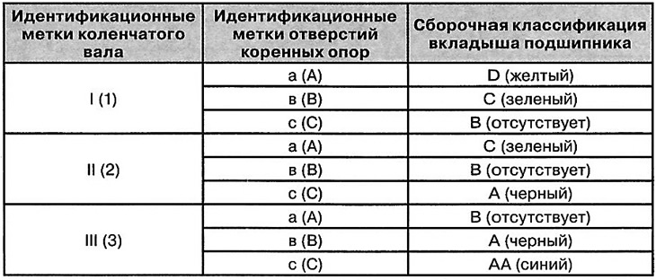
Selection of inserts
3. Measure the clearance in the crankshaft bearings. To do this:
Loosen the mounting bolts and remove the main bearing caps together with the bearing shells.
Clean all main bearings and shells.
Place a special plastic gauge on each main journal of the crankshaft.
Install all main bearing caps and tighten the mounting bolts to a tightening torque of 14.7 Nm+ (27.5-31.4 Nm) + an additional 120-125°.
Caution: Do not turn the crankshaft.
Remove the cover and bearing again, measure the thickness of the plastic gauge (the scale is included with the kit).
Note: Standard size: 0.020 - 0.038 mm.
Location of identification marks on the connecting rod bearing shell
Insert dimensions
 |
 |
If the measurement value is too large or small, remove the upper bearing shell, install a new one, match the bearing to the color of the mark, and recheck the clearance.
Caution: Do not grind or scratch bearings or caps to adjust clearance.
If the gauge shows that the clearance is still not standard, try installing a larger or smaller bearing and check the clearance again.
Note: If the bearing clearance cannot be adjusted by selecting liners, the crankshaft assembly must be replaced and the adjustment repeated.
Caution. If the identification mark on the bearing is not visible due to carbon deposits, it must be washed in solvent. Do not clean the bearing with a scraper or metal brush.
Note:
- When installing, make sure that the number on the connecting rod and its cap matches the cylinder number. When installing a new connecting rod, make sure that the lugs for fixing the bearing match the grooves on the bearing.
- Replace the connecting rod assembly if its side surface is damaged. Also, replace the connecting rod if its working parts show increased wear.
Using special equipment, measure the bending and twisting of the connecting rod. Publishing House "Monolith"
Note:
- Allowable bending value of connecting rod: 0.05mm/100mm or less.
- Allowable twisting of connecting rod: 0.1mm/100mm or less.
- If the permissible bending and twisting values are exceeded, the connecting rod assembly must be replaced.
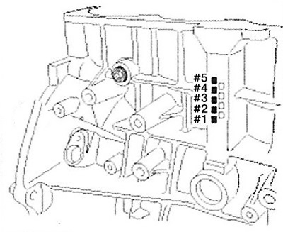
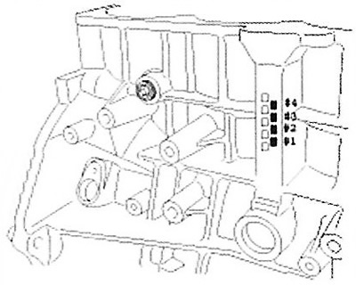
- Location of marks characterizing the inner diameter of the crankshaft main bearings.
Cylinder block
Location of marks on the crankshaft
Crankshaft dimensions (main journals)
Selection of main bearing liners
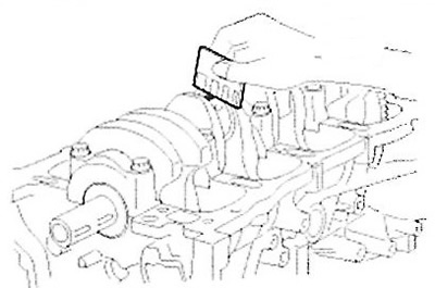
Check the crankshaft end play. Using a dial indicator, measure the crankshaft end play by moving it back and forth with a screwdriver.
Note: Standard axial clearance: 0.07 - 0.25 mm.
Maximum permissible value: 0.30 mm.
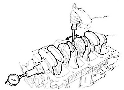
If the axial clearance exceeds the permissible limit, the thrust bearings must be replaced.
Note:
- Thrust bearing thickness: 1.925-1.965 mm.
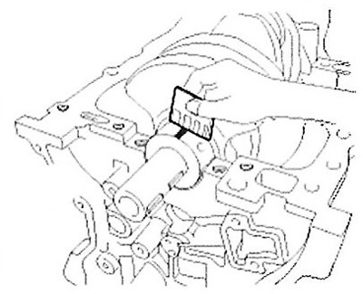
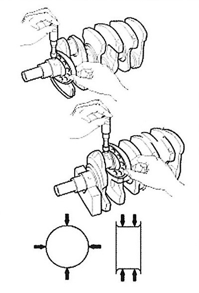
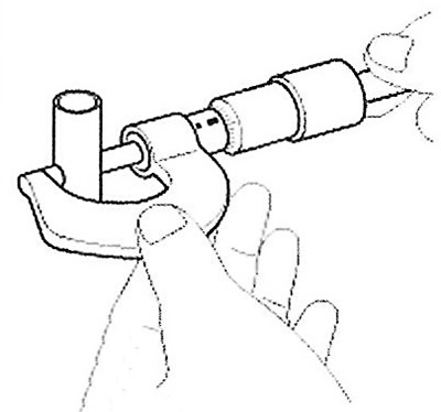
- Using a micrometer, measure the outside diameter of the crankshaft main and connecting rod journals.
Location of identification marks on the main bearing shell
Dimensions of main bearing bearings
Note:
- Crankshaft main journal diameter: 51.942-51.960 mm.
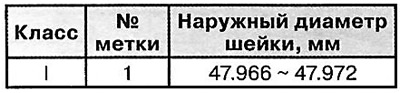
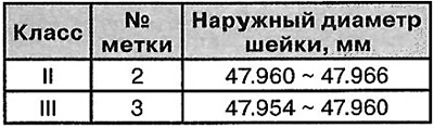
- Crankshaft journal diameter: 47.954-47.972 mm.
Take measurements in two mutually perpendicular planes, as shown in the figure.
Cylinder block
1. Remove any remaining sealant from the cylinder block/head joint surface using a scraper.
2. Using a soft brush and solvent, clean the cylinder block,
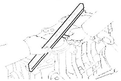
3. Using a special ruler and a set of feeler gauges, measure the non-flatness of the surface of the cylinder block-head joint.
Note: Standard value of non-flatness: less than 0.05mm.
4. Visually inspect the cylinder bore for deep scratches and burrs. If any defects are found, replace the cylinder block assembly.
5. Using a bore gauge, measure the inner diameter of the cylinders in two perpendicular planes in three places.
Note:
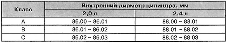
Standard size of internal diameter:
- 2.0 l: 86.00-86.03 mm.
- 2.4 l: 88.00-88.03 mm.
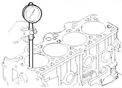
Note: Measurement location (from the bottom of the cylinder block): 110.7mm/160mm/210mm.
6. Check the cylinder size code on the bottom of the cylinder block.
7. Check the piston size code (A) on its bottom (shown in the figure).
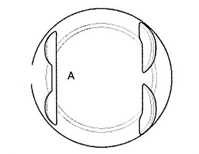
8. Select the piston in relation to the inner diameter of the cylinder block. The gap between the piston and the cylinder should be 0.015 -0.035 mm.
Pistons and piston rings
1. Clean the piston rings.
Using a special scraper, remove carbon deposits from the surface of the rings.
Using a special tool or a broken ring, clean the ring grooves in the piston.
Using solvent and a brush, wash and clean the piston.
Note: Do not use a brush with metal bristles when cleaning.
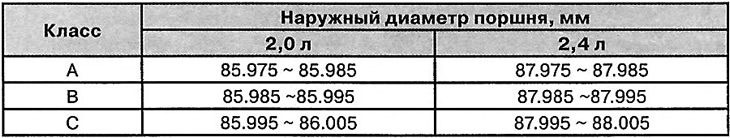
2. Using a micrometer, measure the outside diameter of the piston in the plane of the transverse axis of the piston pin and at a distance of 14 mm from the bottom, as shown in the figure.
Note:
Standard piston diameter:
- 2.0L: 85.975-86.005 mm.
- 2.4L: 87.975-88.005 mm.
3. The difference between the outer diameter of the piston and the inner diameter of the cylinder is the clearance.
Note: Standard value: 0.015-0.035mm.
4. Measure the piston ring side clearance.
Using a set of feeler gauges, measure the gap between the new piston rings and the groove in the piston.
Note:
- Standard side clearance values: 0.05-0.08 mm (compression No.1), 0.04 - 0.08 mm (compression No.2) and 0.06 - 0.15 mm (oil scraper).
- The maximum permissible value of the lateral clearance: 0.1 mm (compression No.1), 0.1 mm (compression No.2) and 0.2 mm (oil scraper).
Note: If the piston ring clearance exceeds the permissible value, the piston assembly must be replaced.
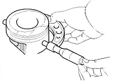
5. Check the clearance in the piston ring joints. To do this:
Install the piston ring into the cylinder. Then, move the ring into the cylinder using the piston as shown in the figure. Measure the gap in the lock using a set of feeler gauges. If the gap in the lock exceeds the permissible limit, it is necessary to replace the ring with a new one. If the gap in the lock is too large, it is necessary to measure the inner diameter of the cylinder. If the cylinder diameter exceeds the permissible norms, it is necessary to replace the cylinder block assembly.
Note:
- Standard ring lock clearance: 0.15-0.30 mm (compression No.1), 0.37-0.52 mm (compression No.2), 0.20-0.70 mm (oil scraper).
- Maximum permissible values: 0.6 mm (compression No.1), 0.7 mm (compression No.2), 0.8 mm (oil scraper).
Piston pins
1. Using a micrometer, measure the outside diameter of the piston pin.
Note: Standard size: 21.001 - 21.006 mm.
2. Measure the clearance between the piston pin and the piston hole.
Note: Standard gap value: 0.013-0.023.
3. Measure the difference between the outside diameter of the piston pin and the inside diameter of the connecting rod head bushing.
Note: Standard size: 0.016 - 0.032 mm.