Note:
- Wash all parts before assembly.
- Before installing parts, apply a thin layer of motor oil to all rubbing surfaces.
- Replace all gaskets, O-rings and seals.
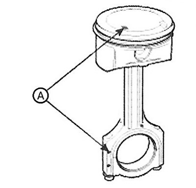
1. Assemble the piston with the connecting rod.
Using a hydraulic press, press the piston pin into the piston.
Make sure that the piston and connecting rod timing marks are facing the timing chain.
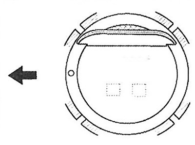
2. Install the piston rings.
Install the oil scraper ring spacer with two side rails, manually.
Using the special tool, install the two compression rings with the identification marks facing upward.
Position the piston rings so that the locks are positioned as shown in the figure below.
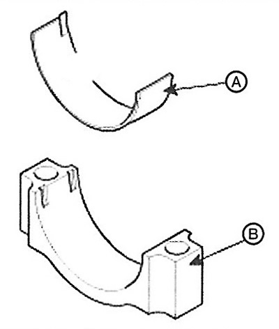
3. Install the connecting rod bearing shells.
Align the protrusion on the bearing shell (A) with the notch on the connecting rod and connecting rod cap (B).
Install the bearing shells into the connecting rod and connecting rod cap as shown in the figure.
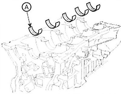
4. Install the main bearing shells.
Note: The upper main bearing shells installed in the cylinder block have grooves for supplying engine oil, while the lower ones do not have grooves.
Align the tabs on the bearing shells with the notches on the cylinder block. Install the bearing shells into the five crankshaft bearings (A) as shown in the figure.
Align the tabs on the bearing shells with the notches on the main bearing caps. Install the bearing shells.
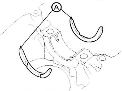
5. Install the thrust bearings on support 3. The liners must be installed with the grooves away from the support, as shown in the figure.
6. Install the crankshaft into the cylinder block.
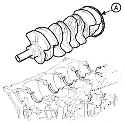
7. Install the main bearing caps on the cylinder block.
8. Install the main bearing cap bolts.
Note:
- Tightening torque: 14.7 Nm + (27.5-31.4 Nm) + (120-125°).
- The main bearing cap mounting bolts are tightened in two steps.
- If any defects in the bolts are found, they must be replaced with new ones.
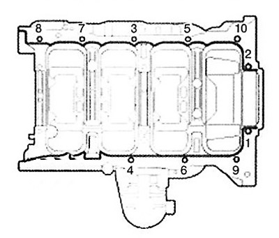
Apply a thin layer of motor oil to the threaded portion of the lug nuts.
Install and tighten the 10 mounting bolts in two steps, in the sequence shown in the illustration.
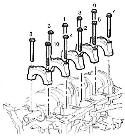
Check and ensure that the crankshaft rotates smoothly.
9. Check the crankshaft axial clearance.
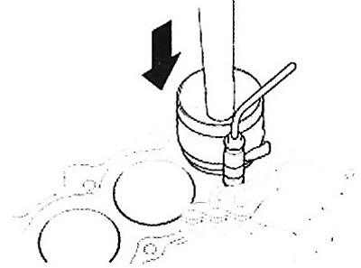
10. Install the pistons together with the connecting rods.
Note: Before installing the pistons into the cylinders, apply a thin layer of engine oil to the ring grooves and cylinder bore.
Remove the connecting rod caps and place a rubber hose over the threaded portion of the connecting rod bolts.
Install a special device for compressing piston rings. Then install the piston in the cylinder and, using light blows from the wooden handle of the hammer, insert it into the cylinder.
Stop when the spring compressor is released. Check that the connecting rod is correctly installed relative to the crankshaft.
Install the connecting rod caps and tighten the mounting bolts.
Note: Tightening torque: (17.7 - 21.6 Nm) + tighten further by 88-92°.
Caution: Always use new bolts.
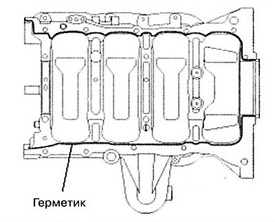
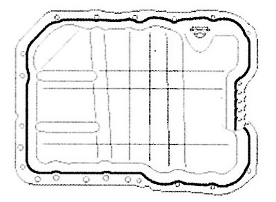
11. Apply sealant to the cylinder block housing joint surface as shown in the figure.
Note: Apply sealant THREE-BOND 1217H or Loctite 5900. Install the crankcase within 5 minutes after applying the sealant. Apply sealant to the threaded portion of the bolt holes.
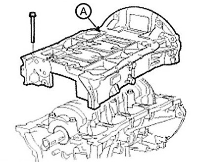
12. Install the crankcase (A) onto the cylinder block. Tighten the mounting bolts to the tightening torque: step 1: 8.8 - 9.8 Nm, step 2: 17.7 -20.6 Nm, step 3: 27.5 - 31.4 Nm.
 |
 |
13. Install the new rear oil seal.
Apply a thin layer of engine oil to the working surface of the seal.
Using a special tool (09231-N1100, 09214-ZK100) and a hammer, press in a new oil seal.
14. Install the balance shaft module (oil pump).
15. Install the water pump.
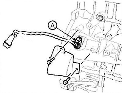
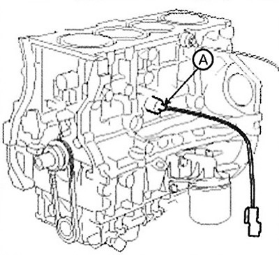
16. Install the crankshaft position sensor (A) and sensor cover (B).
Note: Tightening torque: (A): 9.8- 11.8 Nm.
17. Install the oil pressure sensor.
Apply MS 721-39(B) adhesive to 2 or 3 threads.
Install the oil pressure sensor (A).
Note: Tightening torque: 7.8- 11.8 Nm.
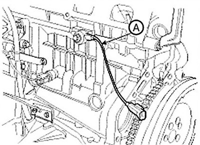
18. Install the knock sensor (A).
Note: Tightening torque: 18.6 - 23.5 Nm.
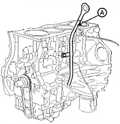
19. Install the oil dipstick.
Install a new O-ring onto the dipstick.
Apply engine oil to the sealing ring.
Install the dipstick (A) with the bolt.
Note: Tightening torque: 7.8-11.8 Nm.
20. Install the integrated tensioner bracket (A).
Note: Tightening torque: 39.2-44.1 Nm.
21. Install the cylinder head.
22. Install the timing chain.
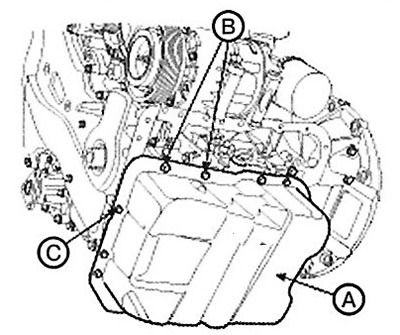
23. Install the oil pan.
Using a blade or scraper, remove the old sealant from the gasket surface.
Note:
- Ensure mating surfaces are clean and dry before applying sealant.
- Apply the sealant with an even roller placed between the edges of the contacting surfaces.
- Use LOCTITE 5900H or THREEBOND 1217H sealant.
Note:
- To prevent oil leakage, it is necessary to apply sealant inside the bolt holes.
- Install the parts within 5 minutes after applying the sealant.
- After assembly, wait 30 minutes, then add oil.
Install the oil pan (A). Install the bolts and tighten in several passes.
21. Install the cylinder head.
Note:
Tightening torque:
- M9 (B): 30.4-34.3 Nm.
- Mb(C): 9.8-11.8 Nm.
24. Remove the engine stand.
25. Install the drive disc (A) (automatic transmission).
Note: Tightening torque: 117.7-127.5 Nm.
Install the flywheel (B) (manual transmission).
(The material was obtained from a web resource: HYUNDAIBOOK.ru)
Note: Tightening torque: 117.7-127.5 Nm.
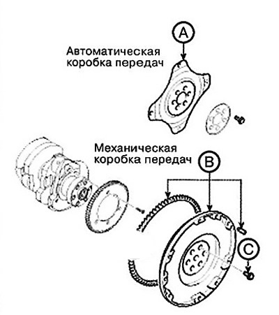
Note:
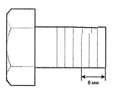
- Always use new flywheel (drive plate) mounting bolts (C).
- Apply sealant to the threaded portion of the new bolts (8 mm from the bottom of the bolt). Sealant: Three bond 2403, Loctite 200 or 204.
- Screw in and tighten the 7 bolts.