
Note: It is not necessary to remove the engine to remove the cylinder head.
Attention.
- To prevent damage to the paintwork of the body wings, it is necessary to use a special coating.
- To prevent damage to the cylinder head, wait until the engine has cooled down before removing it.
- When removing the metal cylinder head gasket, be careful not to drop it or damage the contact surface of the block to the head.
- When disconnecting wiring, apply force directly to the connector, not to the wire.
Note: To avoid incorrect connections, it is necessary to label all wires and hoses.
Turn the crankshaft pulley to set the piston of the first cylinder to the top dead center (TDC) position.
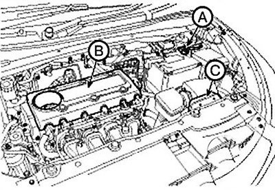
1. Disconnect the negative terminal (A) from the battery.
2. Remove the engine cover (B).
3. Remove the air duct (C).
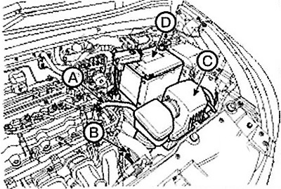
4. Disconnect the breather hose (A), air inlet hose (B) and remove the air cleaner assembly (C).
5. Disconnect the positive terminal (D) from the battery.
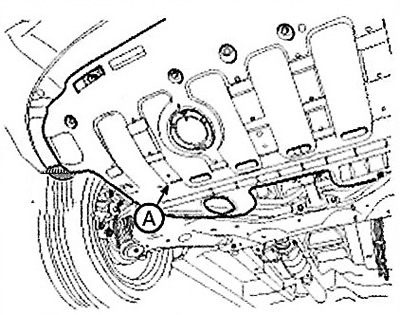
6. Remove the engine protection (A).
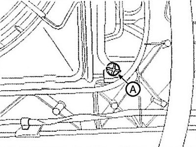
7. Loosen the drain plug (A) and drain the coolant. To speed up the process, remove the radiator cap.
Caution: Never remove the radiator cap when the engine is hot. Otherwise, hot fluid may be ejected from the radiator under high pressure, which may cause severe burns.
8. Remove the upper hose (A) and lower hose (B) of the radiator.
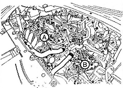
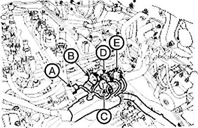
9. Disconnect the wiring connectors and clamps from the engine.
(1) Oil control valve (OCV) connector (A).
(2) Connector (A) of the variable intake manifold geometry system (VIS).
(3) Oil pressure sensor (B) connector.
(4) Knock sensor connector (C).
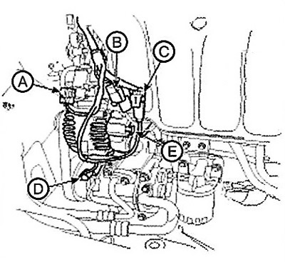
(5) Connector (D) of the air conditioning compressor switch.
(6) Generator connector (E).
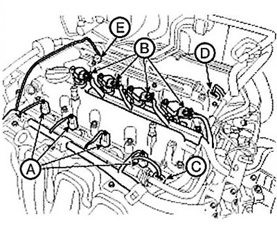
(7) Connectors (A) of injectors
(8) Ignition coil connectors (B).
(9) Connector (C) of the intake camshaft position sensor.
(10) Connector (D) of the exhaust camshaft position sensor.
(11) Connector (E) of the oil supply control valve to the exhaust valves.
(12) Connector (A) of the electronic throttle control (ETC) system.
(13) Connector (B) of the manifold absolute pressure (MAP) sensor and the intake air temperature sensor (IATS).
(14) Connector (A) of the purge control solenoid valve (PCSV).
(15) Connector (B) of the coolant temperature sensor (ECTS).
(16) Capacitor connector (C).
(17) Connector (D) of the crankshaft speed sensor.
(18) Oxygen sensor connector (E).
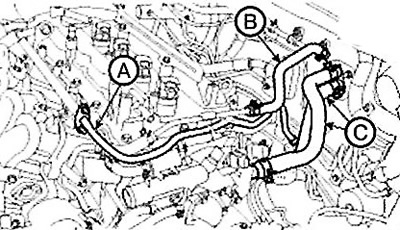
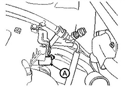
10. Disconnect the fuel hose (A), brake booster vacuum hose (B) and heater hoses (C).
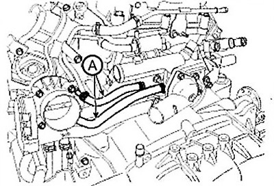
11. Disconnect the cooling system hoses (A) from the throttle body.
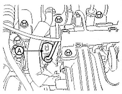
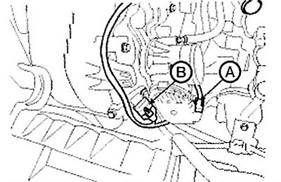
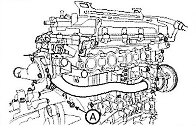
12. Loosen the bolt (A) securing the coolant inlet pipe.
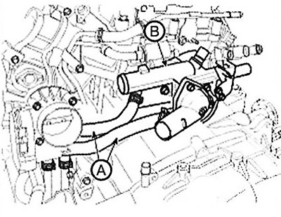
13. Disconnect the oil cooler hoses (A), then remove the coolant outlet block (B).
14. Remove the timing chain.
15. Remove the intake and exhaust manifolds.
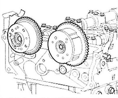
16. Remove the intake and exhaust phase shifters.
17. Remove the camshaft.
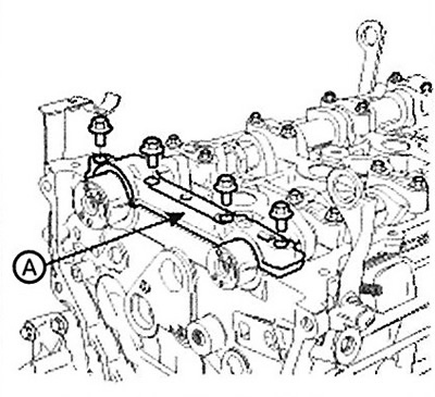
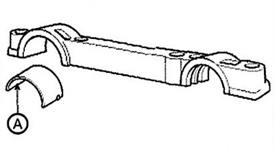
Remove the front camshaft bearing cap (A).
The original text is located on the portal HyundaiBook.ru
Remove the exhaust camshaft upper bearing shell (A).
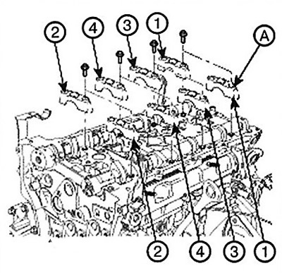
Remove the bearing caps (A) as shown in the figure.
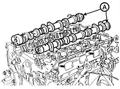
Remove the camshaft (A).
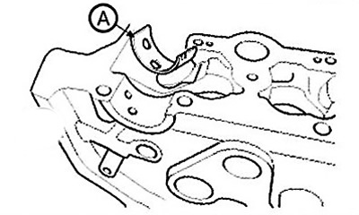
Remove the lower exhaust camshaft bearing shell (A).
18.Remove the oil control inlet valve (A).
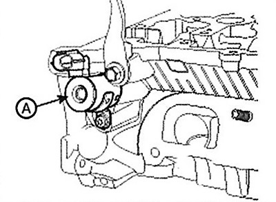
19. Remove the oil control outlet valve.
20. Loosen the cylinder head mounting bolts, then remove the head.
Using the special tool, remove the 10 cylinder head bolts in the order shown in the figure.
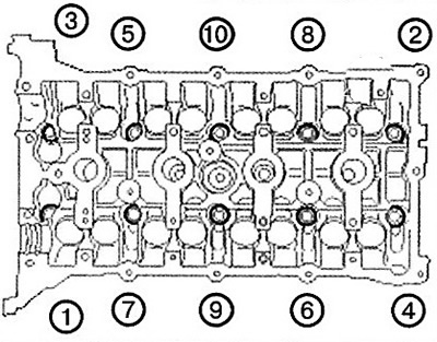
Caution: Incorrect loosening sequence may result in damage to the cylinder head.
Remove the cylinder head from the guide pins on the cylinder block and place it on wooden blocks.
Caution: Be careful not to damage the mating surfaces of the cylinder head and block.
21. Remove the cylinder head gasket.