
Compression check
Note: If there is a loss of power, increased fuel consumption or increased oil consumption, it is necessary to check the compression in the engine cylinders.
1. Warm up and stop the engine. Warm up the engine to normal operating temperature.
2. Disconnect the ignition coil (B) and injector (A) connectors.
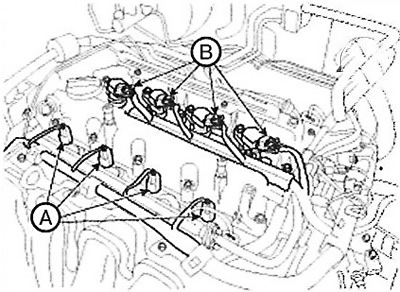
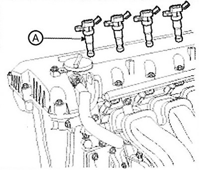
3. Remove the ignition coils (A).
4. Remove 4 spark plugs using a 16mm special wrench.
5. Check the compression in each cylinder.
Install the compression tester into the spark plug hole.
Open the throttle fully.
While turning the crankshaft with the starter, measure the compression.
Note: Make sure the battery is fully charged to provide 200 RPM.
Repeat the above operations for each cylinder.
Note:
- Compression testing should be performed in as little time as possible.
- Standard compression value: 1283 kPa.
- Minimum permissible value: 1135 kPa.
- The difference between the compression of each cylinder is no more than 100 kPa.
If one or more cylinders have insufficient compression, pour a small amount of engine oil through the spark plug hole into the cylinder and repeat steps 1 through 3.
If the compression has increased, it means that the compression rings are damaged or the piston has increased wear.
If the compression has not changed, then the valve seats are probably damaged or the valve is not seated properly. Another possible cause could be a damaged cylinder head gasket.
6. Screw in the spark plugs.
7. Install the ignition coils.
8. Connect the connectors of the injectors and ignition coils.
Checking and adjusting valve clearance
Note: Checking and adjusting the valve clearance must be done on a cold engine (coolant temperature 20°C), with the cylinder head installed on the block.
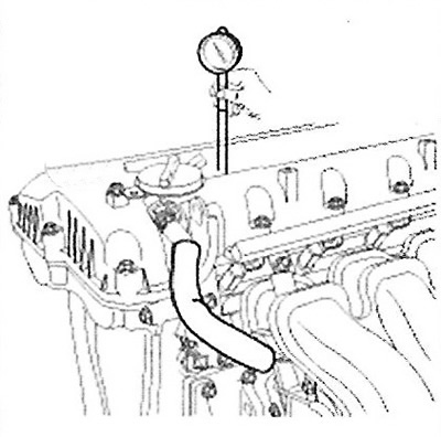
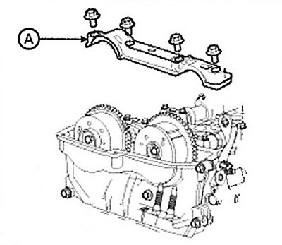
1. Remove the cylinder head cover.
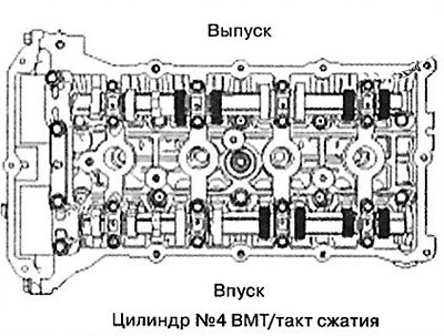
2. Set the piston of the first cylinder to the top dead center position on the compression stroke. To do this:
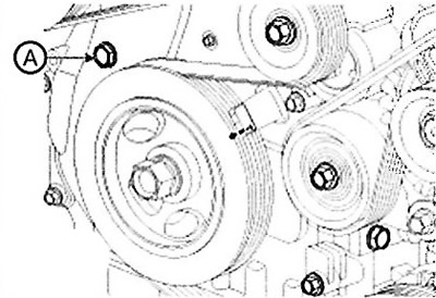
Turn the crankshaft pulley and align the notch on the pulley with the "T" mark on the timing chain cover, as shown in the figure.
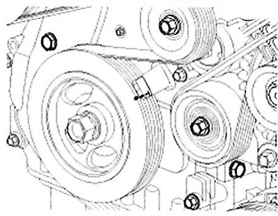
Make sure that the mark on the camshaft sprocket (A) is in line with the plane of the cylinder head. If not, the crankshaft must be rotated 360°.
3. Check the valve clearance.
(1) Check only the intake valve clearances of cylinders 1 and 2, and the exhaust valve clearances of cylinders 1 and 3.
Using a feeler gauge, measure the clearance between the tappet and the base circle of the camshaft.

Note: Valve clearance specification (engine temperature: 20°C):
- Maximum permissible value:
- Inlet valves: 0.10~0.30mm.
- Exhaust valves: 0.20~0.40mm.
(2) Turn the crankshaft pulley one revolution (360° clockwise) and align its groove with the mark on the timing chain cover.
(3) Check the clearances of the intake valves of the 3rd and 4th cylinders, as well as the clearances of the exhaust valves of the 2nd and 4th cylinders.
4. Adjust the clearance of the intake and exhaust valves.
(1) Move cylinder No.1 to top dead center on the compression stroke.
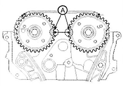
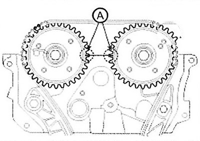
(2) Mark the timing chain links (in 2 places) so that they align with the marks on the intake and exhaust camshaft sprockets.
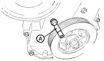
(3) Remove the bolt from the service hole of the timing chain cover.
Caution: Do not reuse a removed bolt.
(4) Insert the thin pin (A) (09240-2G000) into the service hole of the timing chain cover and release the ratchet mechanism.
(5) Remove the front camshaft bearing cap (A).
(6) Remove the exhaust camshaft bearing caps and the exhaust camshaft.
17) Remove the intake camshaft bearing caps and the intake camshaft.
Caution: Hold the timing chain while removing it from the camshaft sprocket.
(8) Tie the timing chain with a thread.
Caution: Do not allow foreign objects to enter the timing chain cover.
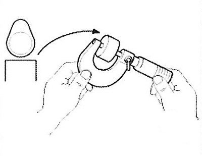
(9) Measure the thickness of the removed tappet using a micrometer.
(10) Calculate the thickness of the new tappet to ensure the valve clearance is within specification.
Valve clearance (engine temperature: 20°C).
T: thickness of the removed pusher.
A: Measured valve clearance. N: Thickness of new tappet. Inlet: N= T + [A - 0.20mm]. Exhaust: N = T + [A-0.30mm].
(11) Select a new pushrod with a thickness as close as possible to the calculated value.
Note: You can use 47 different size adjusting shims in 0.015 mm increments, from 3.00 mm to 3.69 mm.
(12) Install the new tappet into the cylinder head.
(13) While holding the timing chain, install the intake camshaft and phase actuator.
(14) Align the marks on the timing chain with the marks on the camshaft sprocket.
(15) Install the exhaust camshaft.
(16) Install the exhaust camshaft sprocket.
(17) Install the front bearing cover.
Note: Tightening torque: 14.7 Nm.
(18) Tighten the service hole bolt.
Note: Tightening torque: 11.8~14.7Nm.
(19) Turn the crankshaft 2 turns clockwise and re-align the marks (A) of the crankshaft sprocket and camshaft sprocket.
(20) Check the valve clearance.
Note:
- Valve clearance (at engine coolant temperature: 20°C).
- Intake: 0.17 ~ 0.23 mm.
- Outlets: 0.27 ~ 0.33 mm.