
Contents: Tires ⇓ Wheels ⇓ Adjusting the angles of the steering…⇓ Adjusting the rear wheel alignment…⇓
Tires
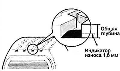
Measuring the tread depth of a tire
1. Measure the tire tread depth. It should be at least 1.6 mm.
2. If the measured depth is less than the maximum allowable depth, replace the tire with a new one.
Note: If the tread depth is less than 1.6 mm, wear indicators appear on the tire.
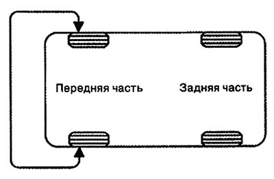
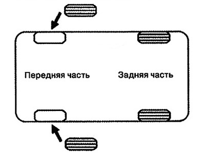
Tire rotation
The tires are replaced according to the diagram shown in the illustration below.
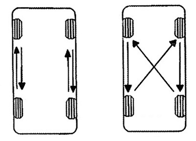
Control of steering force and deviation from the set direction of movement
If the car pulls to one side, rotate the tires.
1. Swap the right and left front wheels and test drive to determine directional stability.
2. If you notice a pull in the opposite direction, swap the front and rear wheels and repeat the test drive.
3. If the vehicle continues to pull in the same direction, it is necessary to swap the right and left front wheels again and conduct another test drive.
4. If there is a pull in the opposite direction, then the front wheels should be replaced.
Wheels
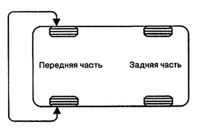
Tightening wheel nuts
Tighten the wheel nuts in the order shown in the illustration.
Note: Tightening torque: 88.3- 107.9 Nm.
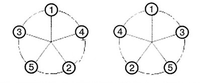
Caution: When using an air impact wrench, the final tightening of the nuts must be checked using a torque wrench.
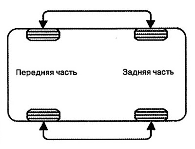
Wheel runout control
1. Raise the car with a jack and secure it with stands.
2. Measure the wheel runout using a dial indicator at the locations shown in the illustration.

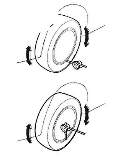
3. If the measured runout values exceed the specified values, the wheel rim must be replaced with a new one.
Adjusting the angles of the steering wheels
Attention.
When using special computerized stands to check the front wheel alignment angles of a vehicle, always place the vehicle on a horizontal surface so that the front wheels are in a straight-ahead position.
Before checking, make sure the front suspension and steering system are in good working order and that all tire pressures are correct.
Convergence
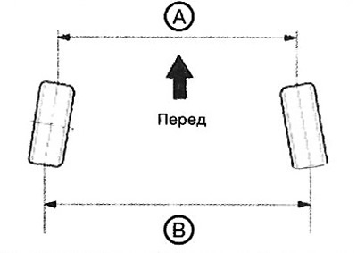
Note:
- B - A > 0: Positive toe-in (+)
- B - A < 0: Positive toe-in (-)
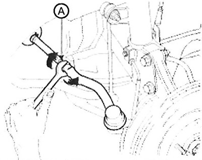
Adjusting the toe-in
1. Loosen the tie rod end lock nut.
2. Loosen the boot clamp to prevent it from twisting.
3. Adjust the toe-in by turning the steering rod (A) to one side or the other. The toe-in should be adjusted equally on the left and right sides.
Note:
Convergence:
- Total: 0° ±0.2°.
- For one wheel: 0° ±0.1°.
4. After completing the toe adjustment, tighten the boot clamp and tighten the tie rod end lock nut to the specified torque.
Note: Tightening torque: 49.0 - 53.9 Nm.
Camber and caster
Camber and caster are preset by the manufacturer, so they do not require additional adjustments. If the camber or caster does not correspond to the nominal value, correct or replace the damaged parts with new ones, then check again.
Note: Camber: -0.5° ±0.5°. Caster: 4.02° ±0.5°.
Adjusting the rear wheel alignment angles
Attention.
When using special computerized stands to check the alignment angles of the rear wheels of a car, always place the car on a horizontal surface so that the front wheels are in a straight-ahead position.
Before checking, make sure the rear suspension and steering system are in good working order and that all tire pressures are correct.
Convergence
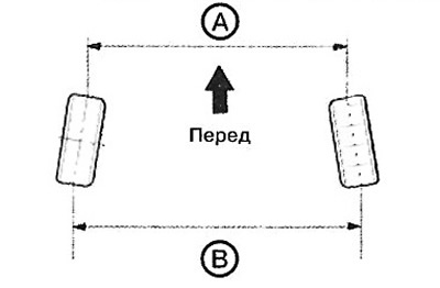
Note:
- B - A > 0: Positive toe-in (+)
- B - A < 0: Positive toe-in (-)
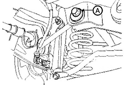
Adjusting the toe-in
1. Loosen the nut securing the eccentric bolt (A) of the sub-arm.
2. Adjust the rear wheel toe-in by turning the eccentric bolt (A) clockwise or counterclockwise.
Note:
Convergence:
- Total: 0.2°+ 0.2°.
- For one wheel: 0.1° ±0.1°.
3. After completing the toe adjustment, tighten the eccentric bolt (A) to the specified torque.
Note: Tightening torque: 100 - 120 Nm.
Camber
The camber is preset by the manufacturer, so it does not require additional adjustments. If the camber does not correspond to the nominal value, correct or replace the damaged parts with new ones, then check again.
Note: Camber: -1.0° ±0.5°.