
Contents: Front wheel alignment angles ⇓ Wheel alignment ⇓ Wheel alignment is adjusted by…⇓ Wheel alignment ⇓ Longitudinal tilt of the pivot axis ⇓ Rear wheel alignment angles ⇓ Adjustment of the rear wheel…⇓ Tire wear ⇓ Wheel runout measurement ⇓ Tightening the wheel nuts ⇓ Wheel rotation ⇓ Checking the exchange rate stability ⇓
Front wheel alignment angles
When checking the front wheel alignment angles using a special device (wheel alignment tester) always park the vehicle on a level, horizontal surface with the front wheels in a straight-ahead position. Before checking, make sure the front suspension, steering and wheels are in good technical condition and the tire pressure is correct.
Wheel alignment
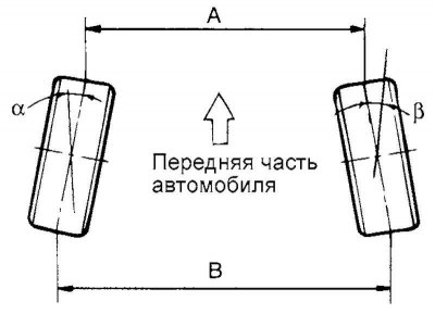
Fig. 4.1. Wheel alignment
Wheel alignment (the difference in dimensions B – A or the sum of angles a + b) is adjusted by rotating the steering rod ends (Fig. 4.1).
To change the toe-in, rotate the right and left tie rod ends by equal angles in opposite directions. The toe-in will decrease as you rotate the left tie rod end toward the rear of the vehicle (and the right tie rod end toward the front of the vehicle).
Toe-in: nominal value – 0±2 mm.
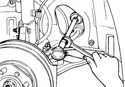
Fig. 4.2. Wheel alignment adjustment
Wheel alignment is adjusted by turning the ends of the left and right steering rods by the same angles (Fig. 4.2).
When adjusting the wheel alignment, loosen the clamps on the steering rod protective boots to prevent the boots from twisting.
After adjustment, tighten the tie rod end locknuts securely and install the boot clamps securely.
Adjust the wheel alignment so that the result is within the range of + 1mm.
Tightening torque of the tie rod end lock nut: 50–55 N·m.
Wheel alignment
The camber of the front wheels is provided by the geometry of the front suspension (the relative position of the steering knuckle and the front suspension strut), i.e. it is adjusted at the manufacturer's factory and is not subject to adjustment during operation.
Wheel alignment: 0° + 301.
Longitudinal tilt of the pivot axis
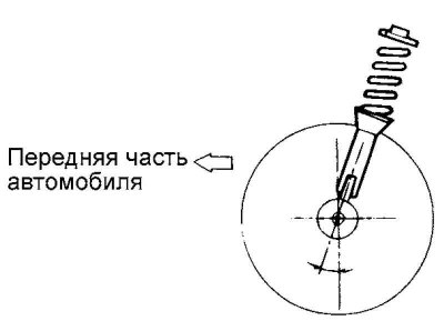
Fig. 4.3. Longitudinal tilt of the pivot axis
The longitudinal tilt of the pivot axis is adjusted at the manufacturer"s factory and cannot be adjusted during operation (Fig. 4.3).
If the longitudinal tilt of the steering axis does not correspond to the nominal value, replace the deformed or damaged suspension parts.
Longitudinal tilt of the pivot axis: 2°49' +30'.
Note: Worn or damaged front suspension components must be replaced before checking wheel alignment.
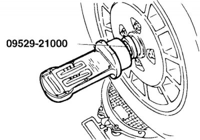
Fig. 4.4. Special tool for measuring wheel alignment angles
A special device is used to measure wheel alignment angles (09529-21000) (Fig. 4.4).
The longitudinal tilt of the steering axis and the camber of the wheels are adjusted at the manufacturer and cannot be adjusted during operation.
If the longitudinal tilt of the steering axis and the camber of the wheels do not correspond to the nominal value, then replace the deformed or damaged suspension parts.
The difference in installation angles (longitudinal tilt of the steering axis and camber of the wheels) between the right and left wheels must be within 0° ±30'.
Rear wheel alignment angles
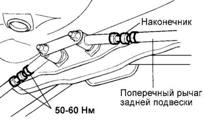
Fig. 4.5. Left wishbone tip
Turning the tip of the left wishbone clockwise increases the wheel alignment (Fig. 4.5).
Turning the right wishbone tip clockwise reduces wheel alignment (see Fig. 4.5).
Nominal value: 3-7 mm.
Adjustment of the rear wheel alignment is made by changing the length (turning the tips) of the transverse suspension arms.
Tire wear
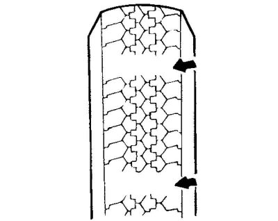
Fig. 4.6. Tire tread depth
Measure the tread depth of your tires (Fig. 4.6).
The text is provided by the web resource: hyundaibook.ru
Tire tread depth (minimum permissible value): 1.6 mm.
If the tread depth is less than the minimum permitted value, replace the tire.
Note: When the minimum tread depth is reached, wear indicator stripes will appear on the tire.
Wheel runout measurement
Raise the wheels of one of the vehicle's axles and install safety stands under the vehicle.
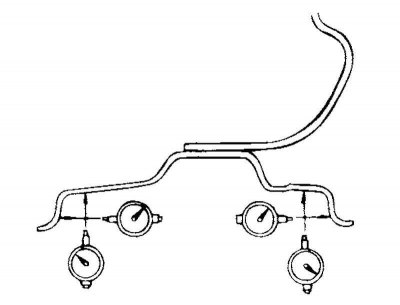
Fig. 4.7. Wheel runout measurement points
Measure the wheel runout using a dial indicator as shown in Figure 4.7.
Replace the wheel if its runout exceeds the maximum permissible value.
Wheel runout (maximum permissible value of radial runout of a steel disk): 0.6 mm.
Aluminum disk:
- Axial - 1.0 mm
- Radial - 0.3 mm
- Axial - 0.3 mm
Tightening the wheel nuts
The tightening torque of the wheel nuts for a wheel with a steel rim and a wheel with an aluminum rim is the same.
Tightening torque: 90–110 Nm.
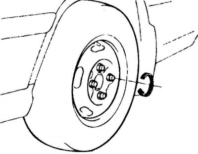
Fig. 4.8. Tightening the wheel nuts
Caution! After tightening the nuts with a pneumatic tool (impact wrench), check the final tightening torque with a torque wrench (Fig. 4.8).
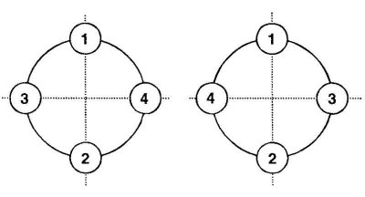
Fig. 4.9. Wheel mounting nuts tightening procedure
The order of tightening the wheel fastening nuts (Fig. 4.9).
Check the tightening torque of the wheel nuts after tightening them to the rated torque in a diagonal sequence.
Wheel rotation
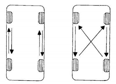
Fig. 4.10. Wheel rotation diagram
When rearranging the wheels, use the diagram shown in Figure 4.10.
Checking the exchange rate stability
If the vehicle pulls to one side while driving, swap the wheels according to the procedure below.
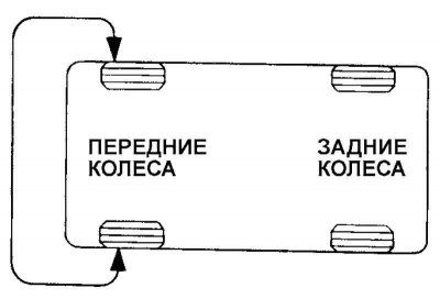
Fig. 4.11. Reinstalling wheels when checking the vehicle's directional stability
Swap the front right and front left wheels, then perform road tests to check the vehicle's directional stability (Fig. 4.11).
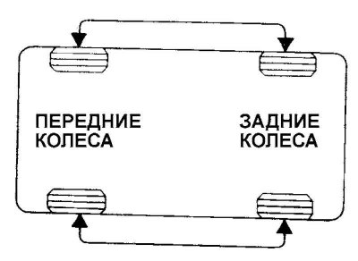
Fig. 4.12. Reinstallation diagram when the car is pulled in the opposite direction
If the car pulls in the opposite direction, swap the front and rear wheels, then perform the road test again (Fig. 4.12).
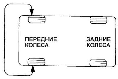
Fig. 4.13. Secondary reinstallation diagram when the vehicle is pulled to the side
If the vehicle pulls to the side, swap the front right and front left wheels again, then perform road tests (Fig. 4.13).
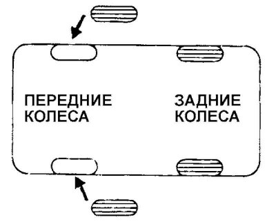
Fig. 4.14. Replacing wheels
If the car pulls in the opposite direction, replace the front wheels with new ones (Fig. 4.14).