
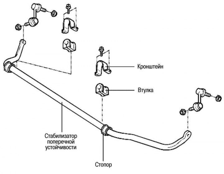
Fig. 4.36. Front anti-roll bar
Removal
Remove the front wheel.
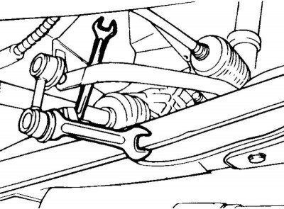
Fig. 4.37. Removing the stabilizer bar
Remove the stabilizer struts as a whole (Fig. 4.37).
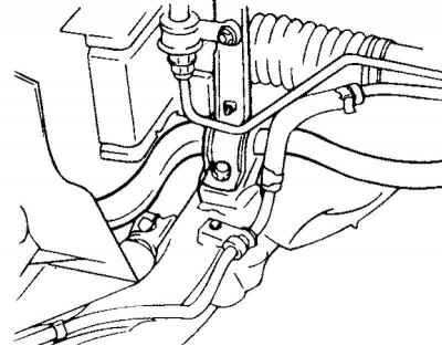
Fig. 4.38. Stabilizer mounting bracket
Remove the stabilizer mounting brackets and stabilizer bushings (Fig. 4.38).
Remove the anti-roll bar.
Examination
Check the anti-roll bar for damage or deformation.
Check all bolts for deformation and damage.
Check the protective covers of the ball joints of the stabilizer struts for cracks and damage.
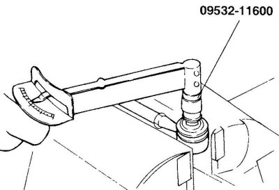
Fig. 4.39. Checking the rotation torque of the stabilizer strut ball joint pin
Check the rotation torque of the stabilizer bar ball joint pin (Fig. 4.39).
If there are cracks or tears in the ball joint protective boot, replace it and add grease to the joint.
Rock the stabilizer bar ball joint pin several times.
Screw the self-locking nut onto the ball joint pin and then measure the pin rotation torque.
Nominal value: 1.7–3.2 Nm.
If the torque exceeds the upper limit of the rated value, replace the stabilizer bar.
If the torque is less than the lower limit of the nominal value, the ball joint is considered fit for further use as long as there is no jamming or excessive clearance in the ball joint.
Installation
Install the bushings on the anti-roll bar.
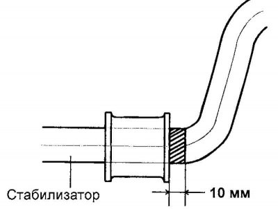
Fig. 4.40. Distance between the edge of the bushing and the edge of the white painted alignment mark
Note: The distance between the edge of the bushing and the edge of the white painted alignment mark on the stabilizer on the outside of the vehicle should be 10 mm (Fig. 4.40).
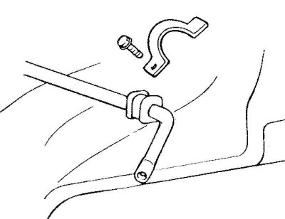
Fig. 4.41. Installing the stabilizer mounting bracket
Install the stabilizer mounting bracket onto the bushing (Fig. 4.41).
Fully align the bushing with the white painted alignment mark on the stabilizer. Temporarily tighten the stabilizer mounting bracket bolts, then install the mounting bracket on the opposite side of the stabilizer.