
HyundaiBook.ru
Repair Chevrolet Repair Honda Repair Toyota Repair Land Rover Repair VAZ Repair Renault Repair Nissan
English Русский
Български
Беларускі
Український
Српски
Hrvatski
Română
Polski
Slovenský
Magyar
ArticlesSitemapContacts  


  Accent   Elantra   Getz   Grandeur   Sonata   Santa Fe   Tucson   Others
Matrix (2001-2010, petrol)
  • Main
  • Hyundai
  • Matrix (2001-2010)
  • Chassis
  • Suspension and wheels
  • Removal and checking the rear suspension trailing arm

Removal and checking the rear suspension trailing arm (Mitsubishi Matrix)

0
Contents: Removal ⇓ Replacing the trailing arm bushing ⇓ Replacing the control arm bushing ⇓ Replacing the rear anti-roll bar ⇓ Examination ⇓
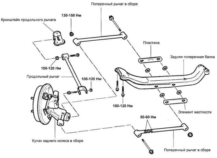
Fig. 4.51. Rear suspension trailing arm

Fig. 4.51. Rear suspension trailing arm


Removal
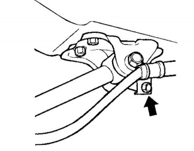


Fig. 4.52. Parking brake cable

Fig. 4.52. Parking brake cable


Disconnect the parking brake cable from the rear suspension trailing arm bracket (Fig. 4.52).
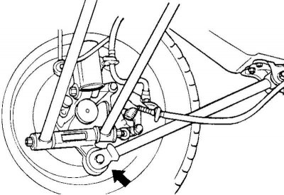
Fig. 4.53. Suspension control arm mounting bolt

Fig. 4.53. Suspension control arm mounting bolt


Loosen the bolt securing the suspension wishbone to the rear wheel knuckle (Fig. 4.53).

Support the rear cross member by placing a jack under its center section, then remove the cross member-to-body bolts.

Remove the rear cross member together with the suspension arms.

Replacing the trailing arm bushing
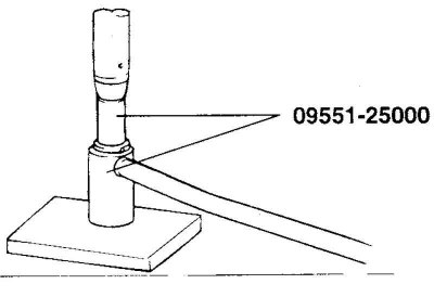


Fig. 4.54. Installing a special tool on the trailing arm of the suspension

Fig. 4.54. Installing a special tool on the trailing arm of the suspension


Install the special tool (09551-25000) on the longitudinal suspension arm (Fig. 4.54).

Remove the trailing arm bushing.
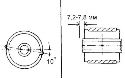
Fig. 4.55. Pressing a new bushing into the trailing arm of the suspension

Fig. 4.55. Pressing a new bushing into the trailing arm of the suspension


Using a special tool (09551-25000) press the new bushing into the trailing arm (Fig. 4.55).
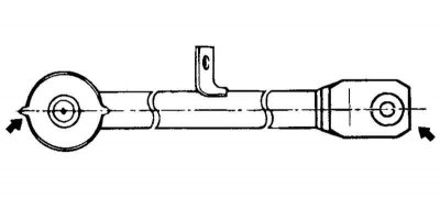
Fig. 4.56. Location of the bushing relative to the lever

Fig. 4.56. Location of the bushing relative to the lever


Note: Press the bushing in place, positioning it relative to the lever as shown in Figure 4.56.


Replacing the control arm bushing
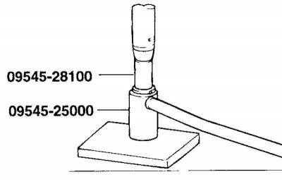


Fig. 4.57. Installing a special tool on the suspension arm

Fig. 4.57. Installing a special tool on the suspension arm


Install the special tool (09545-28100 and 09545-25000) on the control arm (Fig. 4.57).

Remove the control arm bushing.

Wet the contact surfaces of the bushing and the control arm with soapy water.

Using a special tool (09545-25000) press the new bushing into the control arm.

Replacing the rear anti-roll bar


Disconnect the stabilizer struts from the rear suspension strut.
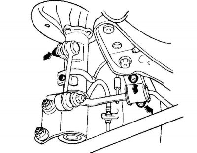
Fig. 4.58. Removing the stabilizer mounting brackets

Fig. 4.58. Removing the stabilizer mounting brackets


[The article is copied from this website HyundaiBook.ru]

Remove the stabilizer mounting brackets (Fig. 4.58).


Remove the anti-roll bar.

Examination
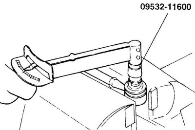


Fig. 4.59. Checking the rotation torque of the stabilizer strut ball joint

Fig. 4.59. Checking the rotation torque of the stabilizer strut ball joint


Check the rotation torque of the stabilizer bar ball joint (Fig. 4.59).

If there are cracks or tears in the ball joint boot, replace it and add grease to the ball joint.

Rock the stabilizer bar ball joint pin several times.

Screw the self-locking nut onto the ball joint pin and then measure the pin rotation torque.

Nominal value: 3.5–4.0 Nm.

If the torque exceeds the upper limit of the rated value, replace the stabilizer bar.

If the torque is less than the lower limit of the nominal value, the ball joint is considered fit for further use as long as there is no jamming or excessive clearance in the joint.
This article is available at russian, bulgarian, belarusian, ukrainian, serbian, croatian, romanian, polish, slovak, hungarian
This article has been reviewed by: Konstantin Smirnov
Add to social network:

Previous
Matrix: Suspension and wheels
Next

Removal, disassembly, inspection and installation of the rear shock absorber strut
Removal, checking and installation the front anti-roll bar
Removal, checking and installation the lower arm of the front suspension
Disassembly, inspection and assembly of the front shock absorber strut
Removal and installation the front shock absorber strut
Table 4.1. Suspension specifications
Table 4.2. Basic data for adjustments and control
Table 4.3. Possible malfunctions, their causes and methods of elimination
We recommend other articles on the topic of Hyundai manuals:

Replacing the rear trailing arm bushing of the rear suspension Hyundai Accent 2 (1999-2005)
Rear suspension trailing arms Hyundai Elantra 3 (2000-2006)
Rear suspension strut Hyundai Getz (2002-2011)
Rear Suspension Specifications and Lubricants Hyundai Sonata 3 (1993-1998)
Rear suspension trailing arm Hyundai Santa Fe 2 (2007-2012, petrol)
Rear suspension trailing arm Hyundai Tucson 2 (2009-2015)

Link in different formats to this article

Visitor comments
No comments yet


How much will 32 + 13 ?


Matrix (2001-2010, petrol) 
  • User manual
  • Control devices
  • Salon equipment
  • Car driving
  • Current service
  • Vehicle specifications
  • Power unit
  • Engine specifications
  • Engine maintenance
  • Engine repair 1.6 l
  • Engine repair 1.8 l
  • Cooling and lubrication system
  • Power and exhaust system
  • Control system
  • Transmission
  • Transmission specifications
  • Clutch
  • Mechanical gearbox
  • Automatic gearbox
  • Drive shafts
  • Chassis
  • Suspension and wheels
  • Steering
  • Brake system
  • Body
  • Exterior (external elements)
  • Passive safety system
  • Heater and air conditioner
  • Electrical equipment
  • Specifications
  • Equipment and devices
  • Power devices
  • Electrical circuits
HyundaiBook.ru © 2018-2026 · Mobile version · Sitemap: EN BG BY UA RS HR RO PL SK HU · Administration · Site search · Hyundai owners Accent 1 · Accent 2 · Accent 3 · Elantra 1 · Elantra 2 · Elantra 3 · Getz · Sonata 3 · Sonata 4 · Santa Fe 2 · Tucson 1 · Tucson 2 · Matrix ·
This site uses cookies to optimize its functionality. By continuing, you agree to our terms.