
Contents: Removal ⇓ Installation ⇓ Replacing the protective cover and…⇓ Replacing the lower control arm "G"…⇓ Examination ⇓
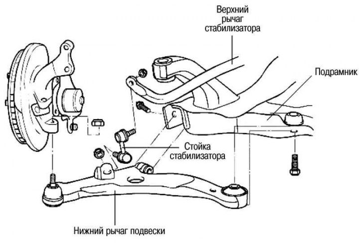
Fig. 4.25. Lower suspension arm
Removal
Remove the front wheel.
Remove the cotter pin, unscrew the wheel drive shaft mounting nut and remove the washer.
Loosen the nut securing the lower suspension arm ball joint to the steering knuckle; do not unscrew the nut completely.
Unscrew the two bolts securing the front strut to the steering knuckle (lower).
Pull the wheel hub outward from the vehicle and separate the wheel drive shaft from it.
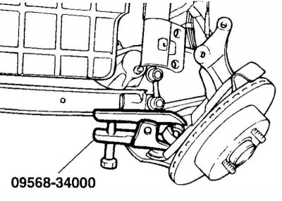
Fig. 4.26. Disconnecting the lower arm ball joint
Using a special tool (09568-34000) disconnect the lower arm ball joint from the lower arm (Fig. 4.26).
Temporarily install the front strut to steering knuckle mounting bolts (lower).
Loosen the stabilizer bar mounting nut.
Unscrew the two bolts securing the bushings "A" and "G" of the lower arm.
Remove the lower control arm assembly.
Installation
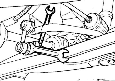
Fig. 4.27. Tightening the self-locking nut
When tightening the stabilizer strut mount, hold the ball joint from turning with a wrench (14 mm), tighten the self-locking nut (Fig. 4.27).
Replacing the protective cover and ball joint of the lower arm
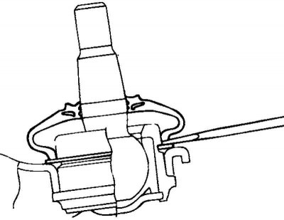
Fig. 4.28. Removing the protective cover from the ball joint of the lower arm
Using a flat-head screwdriver, remove the protective cover from the lower arm ball joint (Fig. 4.28).
Remove the retaining ring.
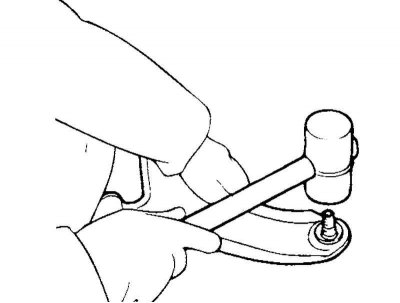
Fig. 4.29. Removing the ball joint from the lower arm
Using a plastic hammer, knock the ball joint out of the lower arm (Fig. 4.29).
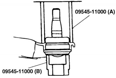
Fig. 4.30. Pressing a new ball joint into the lower arm
Using a special tool (09545-11000) press the new ball joint into the lower arm assembly (Fig. 4.30).
Install the retaining ring.
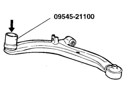
Fig. 4.31. Installing the protective cover
Using a special tool (09545-21000) install the protective cover (Fig. 4.31).
Replacing the lower control arm "G" bushing
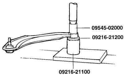
Fig. 4.32. Installing special tools on the lower arm
Install the special tools (09545-02000, 09216-21200 and 09216-21100) on the lower arm (Fig. 4.32).
Press out the bushing.
Wet the following parts with soapy water:
- the outer surface of the bushing;
- the inner mounting surface of the lower arm under the bushing.
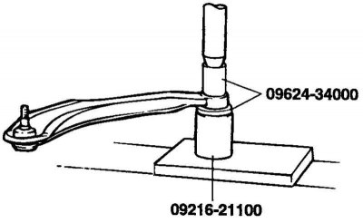
Fig. 4.33. Installing a new bushing on the lower arm
Install a new bushing on the lower arm using the special tool (09216-21100 and 09624-34000) (Fig. 4.33).
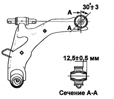
Fig. 4.34. Pressing in the "G" bushing of the lower arm
Note: Press in the lower arm bushing "G" at an angle as shown in Figure 4.34.
Examination
Check the rubber bushings for wear or deformation.
Check the lower control arm for bending or cracks.
Check the ball joint protective cover for cracks and damage.
Check all bolts for deformation and damage.
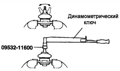
Fig. 4.35. Checking the torque
Check the rotation torque of the lower arm ball joint pin (Fig. 4.35).
If there are cracks or tears in the ball joint protective boot, replace the lower arm ball joint assembly.
Rock the lower arm ball joint pin several times.
Measure the torque of the lower arm ball joint pin.
Nominal value: 3.5–4 Nm.
If the torque exceeds the upper limit of the nominal value, replace the lower arm ball joint assembly.
If the torque is less than the lower limit of the nominal value, then re-installation of this ball joint is allowed, if there is no jamming or excessive play of the hinge pin.