
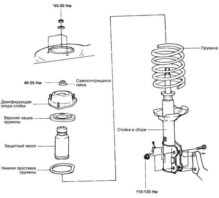
Fig. 4.42. Rear suspension shock absorber strut
Removal
Remove the rear wheels.
Remove the safety cover located in the trunk.
Disconnect the brake hose and wheel speed sensor wire from the rear suspension strut.
Remove the stabilizer struts.
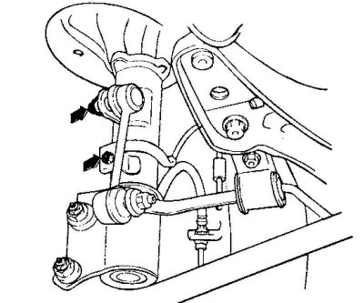
Fig. 4.43. Rear suspension strut mounting bolts
Unscrew the two bolts securing the rear suspension strut to the rear wheel knuckle (Fig. 4.43).
Caution: Be careful not to drop the rear pillar.
Remove the rear strut assembly from the vehicle.
Disassembly
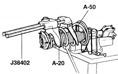
Fig. 4.44. Compression of the shock absorber spring
Using a special tool (J38402, A-20 and A-50), compress the strut spring so that the impact on the spring cups is minimal (Fig. 4.44).
Note: Do not use air tools (impact wrench).
Loosen the self-locking nut at the top end of the shock absorber rod.
Remove the strut damper support, upper spring cup, spring and boot from the strut assembly.
Examination
Check the strut damper support for wear or damage.
Check rubber parts for damage or deterioration.
Check the spring and strut assembly for wear or deformation (sagging and loss of rigidity).
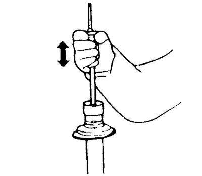
Fig. 4.45. Checking the shock absorber
Check the shock absorber for abnormal resistance to rod movement and extraneous noise (Fig. 4.45).
Assembly
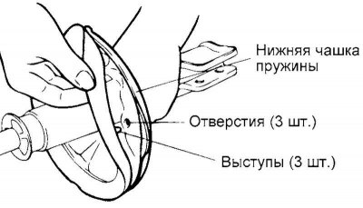
Fig. 4.46. Installing the lower spring spacer
Install the lower spring spacer so that the protrusions on it are aligned with the holes in the lower spring cup (Fig. 4.46).
Install the protective cover on the shock absorber.
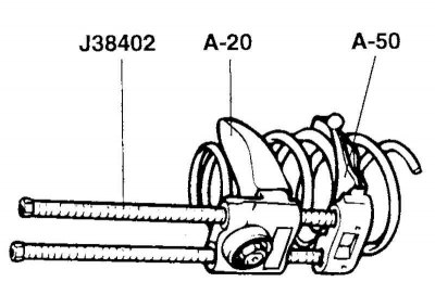
Fig. 4.47. Spring compression
Using a special tool (J38402, A-42), compress the spring (Fig. 4.47).
Extend the shock absorber rod to the stop, install the upper spring cup and the damping support of the strut assembly.
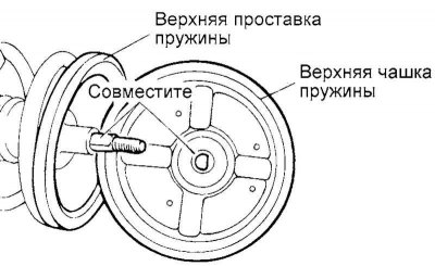
Fig. 4.48. Alignment of the flat part of the D-shaped hole of the upper spring cup
Note: Align the flat portion of the D-shaped hole in the upper spring cup with the flat portion of the unthreaded portion of the shock absorber piston rod (Fig. 4.48).
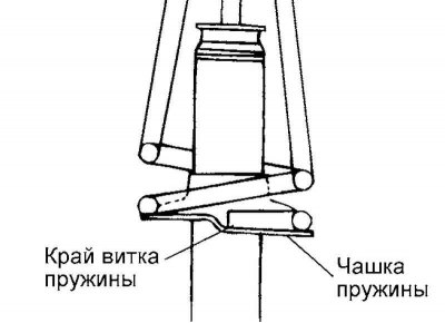
Fig. 4.49. Alignment of the upper and lower spring coils
Align the upper and lower spring coils with the corresponding recesses on the upper and lower strut spring cups, then temporarily tighten the self-locking nut (Fig. 4.49).
Caution: Replace the self-locking nut with a new one after removing.
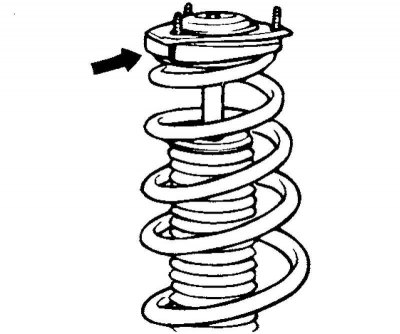
Fig. 4.50. Location of the shock absorber support of the rack
When installing, position the strut damper support so that its bolt is aligned with the protrusion of the upper spring cup, as shown in Figure 4.50.
Remove the special tool (J38402, A-20 and A-50).
Tighten the self-locking nut to the specified torque of 40–55 N·m.