
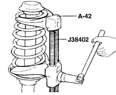
Fig. 4.19. Compression of the strut spring
Using a special tool (J38402, A-42), compress the strut spring so that the impact on the spring cups is minimal (Fig. 4.19).
Note: Do not use air tools (impact wrench).
Unscrew the nut at the upper end of the shock absorber rod.
Remove the strut damper support, upper spring cup, spring and boot from the front strut assembly.
Examination
Check the strut damper bearing for wear or damage.
Check rubber parts for damage or deterioration.
Check the spring for wear or deformation (sagging and loss of rigidity).
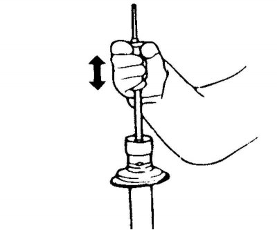
Fig. 4.20. Checking the shock absorber
Check the shock absorber for abnormal resistance to rod movement and extraneous noise (Fig. 4.20).
Rack disposal
Extend the shock absorber rod until it stops.
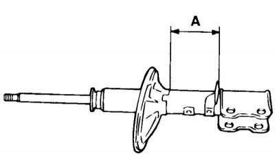
Fig. 4.21. Gas release hole
Drill a hole at the location marked "A" in Figure 4.21 and release the gas from the shock absorber.
Warning! The gas itself is harmless, but when it comes out of the hole, chips left after drilling may fly out, so be careful.
Assembly
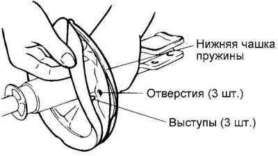
Fig. 4.22. Installing the lower spring spacer
Install the lower spring spacer so that the protrusions on it are aligned with the holes in the lower spring cup (Fig. 4.22).
Install the protective cover on the shock absorber.
Using the special tool (J38402, A-42), compress the spring.
After the spring is fully compressed, install it on the shock absorber.
Note: Install the spring so that the identification mark is located on the steering knuckle side.
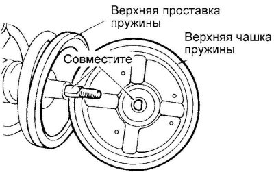
Fig. 4.23. Installing the upper spring cup and the strut damper support
Extend the shock absorber rod to the stop, install the upper spring cup and the damping support of the strut assembly (Fig. 4.23).
Note: Align the flat portion of the D-shaped hole in the upper spring cup with the flat portion of the unthreaded portion of the shock absorber piston rod.
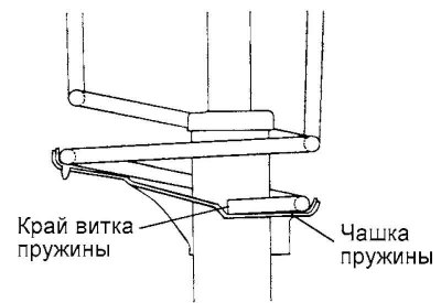
Fig. 4.24. Spring coil alignment marks
Align the upper and lower spring coils with the corresponding recesses on the upper and lower strut spring cups, then temporarily tighten the self-locking nut (Fig. 4.24).
Remove the special tool.
Tighten the self-locking nut to a specified torque of 50–70 N·m.
Apply the specified grease to the strut damper bearing and install the protective cap.
Caution! Be careful when applying lubricant, do not allow it to come into contact with the rubber part of the damper support.
Recommended grease: MS511-11 or equivalent.