
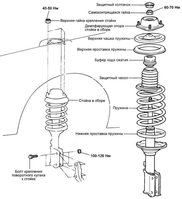
Fig. 4.12. Front strut assembly
Removal
Remove the wheel.
Disconnect the brake hose bracket from the front strut assembly.
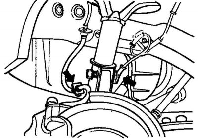
Fig. 4.13. Brake hose bracket and wheel speed sensor
Remove the wheel speed sensor from the steering knuckle and disconnect the sensor wire from the front strut (Fig. 4.13).
Caution: Be careful not to damage the wheel speed sensor.
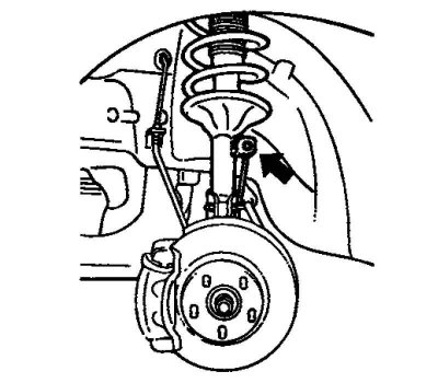
Fig. 4.14. Fastening the anti-roll bar
Remove the anti-roll bar (Fig. 4.14).
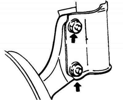
Fig. 4.15. Fastening the steering knuckle arm
Remove the steering knuckle arm from the strut assembly (Fig. 4.15).
(This article is based on information from the website: HyundaiBook)
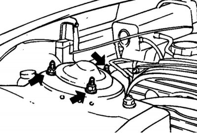
Fig. 4.16. Upper rack mounting nuts
Remove the three upper strut mounting nuts (Fig. 4.16).
Remove the rack assembly.
Installation
Installation is carried out in the reverse order of removal.
Disassembly
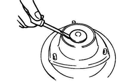
Fig. 4.17. Removing the protective cap
Remove the protective cap from the stand using a flat-head screwdriver (Fig. 4.17).
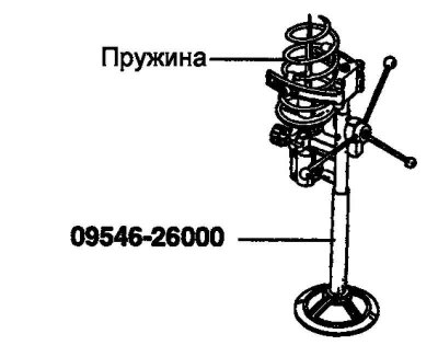
Fig. 4.18. Compressing the spring using a special tool
Using a special tool, compress the strut spring so that the impact on the spring cups is minimal (Fig. 4.18).
Note: Do not use air tools (impact wrench).
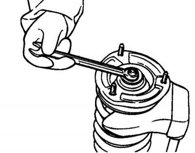
Fig. 4.19. Removing the self-locking nut
Remove the self-locking nut (Fig. 4.19).
Remove the washer, strut damper assembly, upper spring cup, upper spring spacer, compression bump stop, boot, spring and lower spring spacer.
Examination
Check rubber parts for damage or deterioration.
Check the spring for wear or deformation (sagging and loss of rigidity).
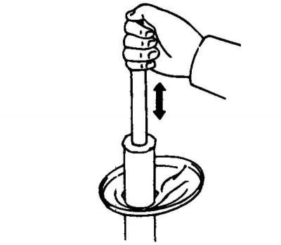
Fig. 4.20. Checking the operation of the shock absorber rod
Take the shock absorber rod and press. Move the shock absorber rod up and down several times (Fig. 4.20).
Check the shock absorber for extraneous noise and abnormal resistance to rod movement.
Check the shock absorber for damage or fluid leaks.
Rack disposal
Extend the shock absorber rod until it stops.
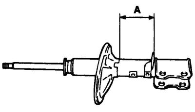
Fig. 4.21. Section of the shock absorber body for drilling a hole
Drill a hole at the location marked "A" in Figure 4.21 and release the gas from the shock absorber.
Warning! The gas itself is harmless, but when it comes out of the hole, chips left after drilling may fly out, so be careful.
Assembly
Using a suspension spring compressor, fully compress the strut spring.
Note: Do not use air tools (impact wrench).
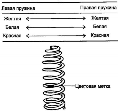
Fig. 4.22. Shock absorber spring color marks
Install a spring that matches the load classification (Fig. 4.22).
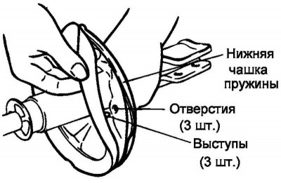
Fig. 4.23. Aligning the lower spacer with the holes in the lower spring cup
Install the lower spring spacer so that the protrusions align with the holes in the lower spring cup (Fig. 4.23).
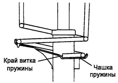
Fig. 4.24. Aligning the edge of the spring coil with the cup
Note: Align the upper and lower end coils of the spring with the corresponding notches on the upper and lower cups of the strut (Fig. 4.24).
Install the upper spring cup onto the shock absorber rod.
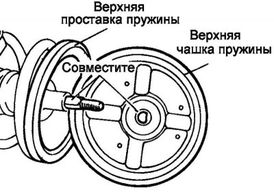
Fig. 4.25. Aligning the flat part of the D-shaped hole of the upper spring cup with the chamfer of the threadless part of the shock absorber rod
Note: Align the flat portion of the D-shaped hole in the upper spring cup with the flat portion of the unthreaded portion of the shock absorber piston rod (Fig. 4.25).
Temporarily install a new self-locking nut.
Remove the special tool.
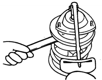
Fig. 4.26. Tightening the shock absorber rod self-locking nut
Tighten the self-locking nut to the specified torque (Fig. 4.26).
Tightening torque of the self-locking rod nut: 60–70 N·m.
Caution: Do not damage the shock absorber rod with the tool.