
Contents: Verification procedures ⇓ Front wheel alignment angles ⇓ Wheel alignment (toe-in) ⇓ Convergence B–A ⇓ Adjusting the slip and turning…⇓ Wheel alignment (camber) ⇓ Longitudinal tilt of the rotation…⇓ Rear wheel alignment angles ⇓ The lower arm of the rear suspension…⇓ Wheel alignment ⇓ Checking tire wear ⇓ Checking wheel runout ⇓ Tightening the wheel nuts ⇓
Verification procedures
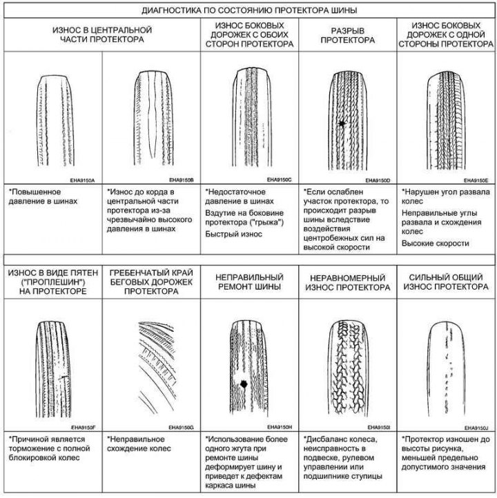
Fig. 4.1. Diagnostics based on tire tread condition
Conduct diagnostics based on the condition of the tires (Fig. 4.1).
Front wheel alignment angles
When checking the front wheel alignment angles using a special device (wheel alignment tester) always park the vehicle on a level, horizontal surface with the front wheels in a straight-ahead position. Before checking, make sure the front suspension, steering and wheels are in good technical condition. Also check that the wheels are in a straight-ahead position and the tire pressure is correct.
Wheel alignment (toe-in)
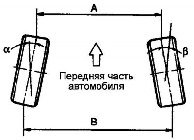
Fig. 4.2. Wheel alignment
Wheel toe-in (the difference in dimensions B–A or the sum of angles a + b) is adjusted by rotating the tie rod ends. To change wheel toe-in, rotate the right and left tie rod ends by equal angles in opposite directions. The toe-in will decrease as you rotate the left tie rod end toward the rear of the vehicle (and the right tie rod end toward the front of the vehicle).
Convergence B–A
Nominal value: 0±2 mm.
Adjusting the slip and turning angles of the steering wheels (side slip and steering angle)
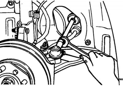
Fig. 4.3. Adjusting the slip and turning angles of the steering wheels
The sliding is adjusted by rotating the side steering rod.
The wheel turning angles are adjusted by the nominal torque, rotating the right and left side steering rods in opposite directions to certain angles.
External wheel turning angle: 32°73' ±2.
Inner wheel turning angle (the difference between left and right should be no more than 2°): 37°41' ±2.
The difference in the internal angles of rotation of the wheels by means of torsion: 0.65°.
Tightening torque of the side tie rod lock nut: 50–55 N·m.
Note: Remove the boot clamps before turning the tie rods.
Note: Check the boot mounts for twisting after installing the tie rod.
Wheel alignment (camber)
The camber of the front wheels is provided by the geometry of the front suspension (the relative position of the steering knuckle and the front suspension strut), i.e. it is adjusted at the manufacturer's factory and is not subject to adjustment during operation.
Wheel alignment: 0° ±30'.
Longitudinal tilt of the rotation axis (caster)
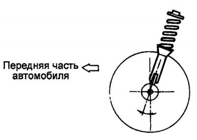
Fig. 4.4. Longitudinal tilt of the pivot axis
The longitudinal tilt of the steering axis is adjusted at the factory and is not subject to adjustment during operation. If the longitudinal tilt of the steering axis does not correspond to the nominal value, replace the deformed or damaged suspension parts.
Longitudinal tilt of the steering axis: 2°30' ±30'.
Note: Worn or damaged front suspension components must be replaced before checking wheel alignment.
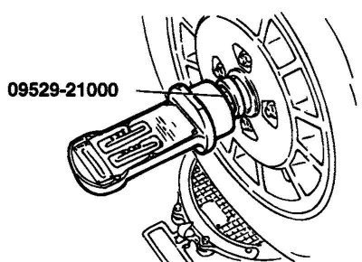
Fig. 4.5. Measuring wheel alignment angles
A special device is used to measure wheel alignment angles (09529-21000) (Fig. 4.5).
The longitudinal tilt of the steering axis and the camber of the wheels are adjusted at the manufacturer and cannot be adjusted during operation.
If the longitudinal tilt of the steering axis and the camber of the wheels do not correspond to the nominal value, then replace the deformed or damaged suspension parts.
Rear wheel alignment angles
Toe-in: 0 ±2 mm.
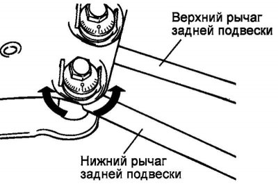
Fig. 4.6. Adjusting the lower suspension arm by rotating the cam bolt
The lower arm of the rear suspension is adjusted using a cam bolt (Fig. 4.6).
Left wishbone tip: Turning clockwise increases wheel toe-in.
Right wishbone tip: Turning clockwise decreases wheel toe-in.
When adjusting the toe-in, the cam bolt (cam bolt) should be turned left or right no more than 90° from the center position.
Wheel alignment
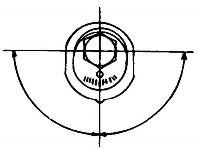
Fig. 4.7. Adjusting the upper suspension arm by rotating the cam bolt
The upper arm of the rear suspension is adjusted using a cam bolt (Fig. 4.7).
Install the left and right springs according to the color marks.
When adjusting the toe-in, the cam bolt (cam bolt) should be turned left or right no more than 90° from the center position.
Wheel camber: 0°30' ±30'.
Checking tire wear
Measure the tread depth of your tires.
Tire tread depth (minimum permissible value): 1.6 mm
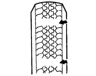
Fig. 4.8. Tread pattern height
If the tread depth is less than the minimum permissible value, replace the tire (Fig. 4.8).
Note: When the minimum tread depth is reached, wear indicator stripes will appear on the tire.
Checking wheel runout
Raise the wheels of one of the vehicle's axles and install safety stands under the vehicle.
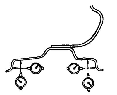
Fig. 4.9. Wheel runout test diagram
Measure the wheel runout using a dial indicator as shown in Figure 4.9.
Replace the wheel if its runout exceeds the maximum permissible value.
Wheel runout (maximum permissible value, steel disk):
- radial - 0.6 mm;
- axial - 1.0 mm.
Aluminum disk:
- radial - 0.3 mm;
- axial - 0.3 mm.
Tightening the wheel nuts
Tightening torque of wheel nuts: 90–110 Nm.
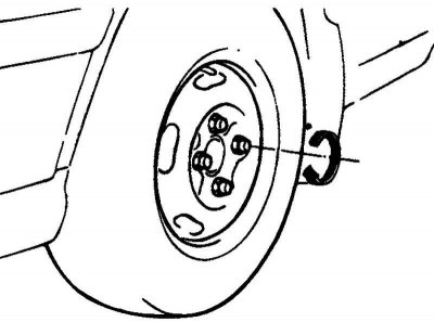
Fig. 4.10. Tightening the wheel nuts
Note: After tightening the nuts with a pneumatic tool (impact wrench), the final tightening torque should be checked with a torque wrench (Fig. 4.10).
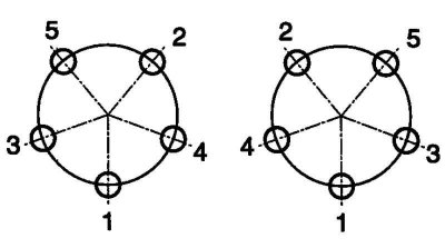
Fig. 4.11. Wheel mounting nuts tightening procedure
Tighten all wheel nuts in the sequence shown in Figure 4.11.