
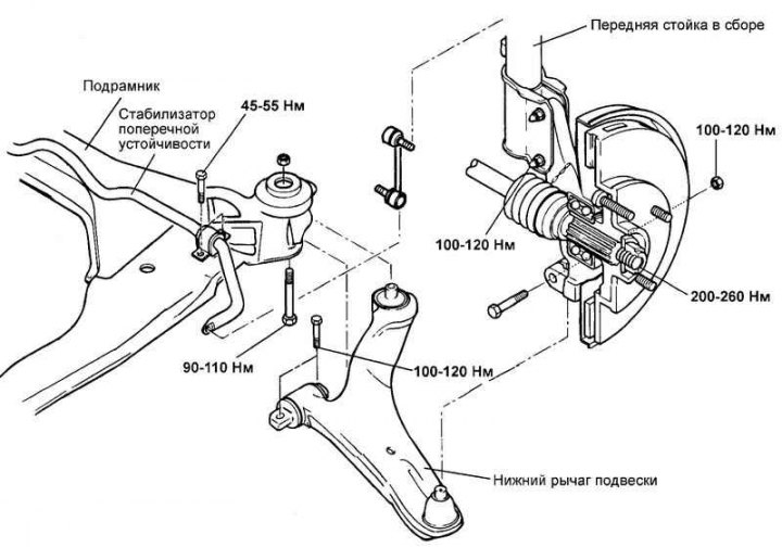
Fig. 4.27. Components of the front suspension lower arm
Removal
Remove the front wheel.
Loosen the bolt securing the lower suspension arm ball joint to the steering knuckle.
Remove the three bolts securing the lower control arm to the subframe.
Installation
Installation is carried out in the reverse order of removal.
Disassembly
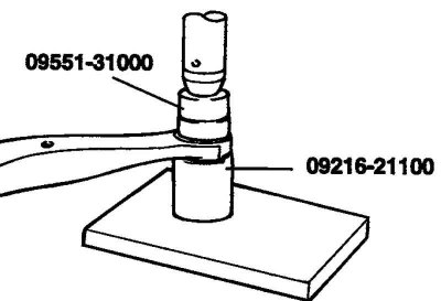
Fig. 4.28. Removing the lower suspension arm bushing
Using a special tool, remove the lower suspension arm bushing (Fig. 4.28).
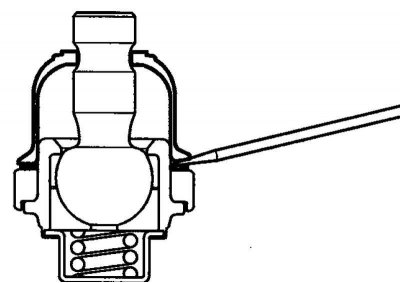
Fig. 4.29. Removing the protective cover of the ball joint of the lower suspension arm
Using a flat-head screwdriver, remove the protective cover of the lower suspension arm ball joint (Fig. 4.29).
Remove the retaining ring.
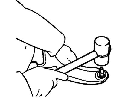
Fig. 4.30. Removing the ball joint from the lower suspension arm assembly
Using a plastic hammer, remove the ball joint from the lower control arm assembly (Fig. 4.30).
Examination
Check the bushing for wear and deformation.
Check the lower control arm for bends or other damage.
Check the ball joint boot for cracks. If the boot is cracked, replace the ball joint assembly.
Check the lower control arm connecting bolt.
Rock the lower control arm ball joint pin several times to check for looseness.
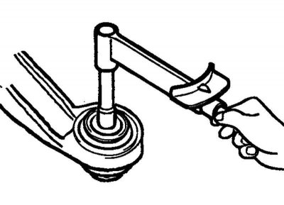
Fig. 4.31. Measuring the torque of the lower arm ball joint pin
Check the rotation torque of the lower arm ball joint pin (Fig. 4.31).
Nominal torque: 1.5–3.5 Nm.
If the pin torque exceeds the rated torque, replace the ball joint assembly.
If the pin rotation torque is less than the rated torque, the ball joint can be used further if there is no damage.
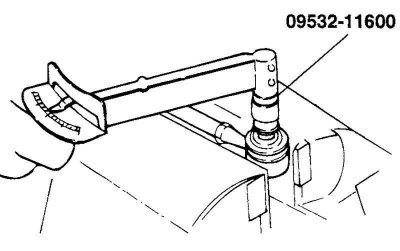
Fig. 4.32. Checking the rotation moment of the anti-roll bar ball joint
Check the initial rotation moment of the anti-roll bar ball joint (Fig. 4.32).
If there are cracks or tears in the ball joint boot, replace it and add grease to the ball joint.
Rock the stabilizer bar ball joint pin several times to check for looseness.
Screw the self-locking nut onto the ball joint pin and measure the initial torque.
Nominal torque: 0.7–2.0 Nm.
If the pin torque exceeds the rated torque, replace the stabilizer bar. If the pin torque is less than the rated torque, the ball joint can be used further if there is no wear or excessive cracks.
Assembly
Using a special tool, press in the lower control arm bushing.
Note: Nominal force for pressing the bushing: more than 50 N
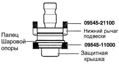
Fig. 4.33. Ball joint pin pressing diagram
While holding the ball joint pin, press the pin into the lower suspension arm bushing (Fig. 4.33).
Note: Do not press the ball joint protective cover.
Using pliers, install the snap ring.
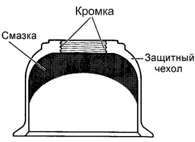
Fig. 4.34. Scheme of applying lubricant to the inner edge of the protective cover
Apply grease to the inner edge of the protective boot and to the inside of the protective boot (Fig. 4.34).
Lubricant: Sunlight MB-2 or equivalent.
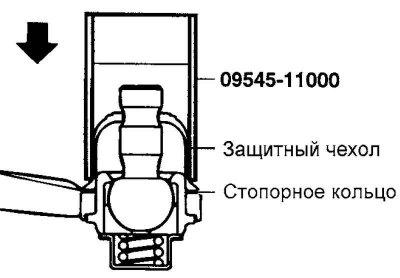
Fig. 4.35. Protective cover installation diagram
Using a special tool, install the protective cover in place and secure it with the retaining ring (Fig. 4.35).