
Contents: Sensor ⇓ Receiver ⇓
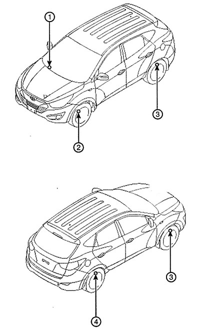
1. Receiver
2. Tire pressure monitoring system sensor
3. Tire pressure monitoring system sensor
4. Tire pressure monitoring system sensor
5. Tire pressure monitoring system sensor
Sensor
Removal
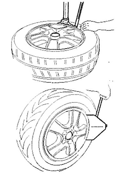
Removal the tire
1. Deflate the tire and remove the balancing weights.
Note: The sensor can be unscrewed before removing the tire bead.
Attention.
The tire bead should be torn off at an angle of approximately 90° relative to the valve.
When removing the tire, do not allow the valve to come into contact with the tire or tool.
The side tear should end near the valve.
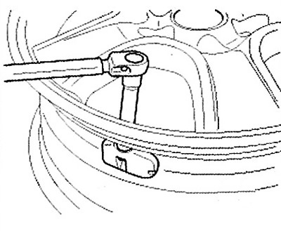
Removal the sensor
Attention: Please handle the consignor with the utmost care and caution.
1. Unscrew the valve nut.
Caution: The removed valve nut cannot be reused.
Installation
Installing the sensor
Attention.
Handle the sensor with extreme care and caution.
Avoid contact with lubricants.
Make sure that the wheel you are mounting is designed to accommodate the sensor. This is usually indicated on the wheel rim marking.
Clean the valve hole and the mating surface of the rim.
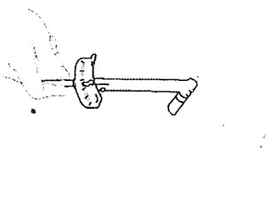
1. Install the sensor and valve assembly into the rim valve hole. Press the sensor against the rim and the rubber bushing against the sealing surface.
2. Place the nut on the valve fitting.
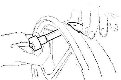
3. Continue tightening the nut until it touches the rim, then tighten it to a torque of 3.5-4.5 Nm.
Attention.
Tighten the nut slowly, a quarter turn at a time, until the required torque is reached.
Do not exceed the permissible tightening torque.
Do not use electric or pneumatic impact wrenches.
4. Make sure the sensor fits tightly on the rim.
Caution: If the sensor is not tightly seated on the rim, there is an increased risk of damage during tire installation/removal.
5. Inflate the tire and install the valve cap.
Attention.
Using the GDS scanner, change the status of the newly installed sensor to "Normal Fixed Base" (Low Line).
The installed sensor must be in the mode (parameter "Status") "Normal Fixed Base" (Normal state of the fixed base) (Low Line).
Receiver
Replacement
Note: Supplied receiver: Replacement
1) Must be in an unprogrammed state.
2) Should not be customized for any specific platform.
3) Should not store sensor identifiers in memory.
Caution: To ensure that the tire pressure warning thresholds are set correctly, it is important that the replacement receiver is selected correctly. It must be of the "Low Line" type, not the "High Line" type.
1. Disconnect the wires from the battery.
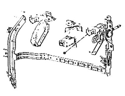
2. Remove the glove box.
3. Remove the faulty receiver and install the bracket on the new one.
4. Install the new receiver on the vehicle and connect the connector.
5. Connect the wires to the battery and turn on the ignition.
6. Check that the flashing frequency of the tire warning light matches the displayed "Virgin" status.