


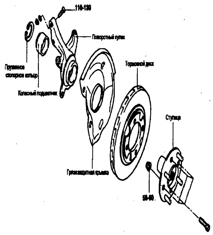
Removal
Note:
- Before removing the front axle assembly, disconnect the ABS wheel sensor and move it beyond the front axle.
- Failure to perform this operation may result in damage to the sensor wires, rendering the sensor inoperative.
1. Remove the drive shaft nut.
2. Raise the vehicle on a lift and place supports under the lift.
3. Remove the wheel.
4. Remove the brake assembly and hang it with wire.
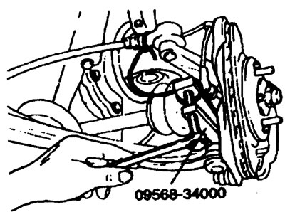
Note: It is not necessary to disconnect the brake hose from the wheel brake cylinder. Be careful not to press the brake pedal or the piston will fall out.
5. Disconnect the lower arm ball joint from the steering knuckle using a special tool.
6. Disconnect the ball joint of the tie rod from the steering knuckle using a special tool.
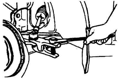
7. Disconnect the drive shaft from the hub using a special tool.
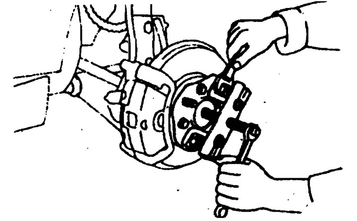
8. Remove the hub and steering knuckle assembly from the suspension strut.
Examination
1. Check the hub for cracks and spline wear.
2. Check the snap ring for cracks and damage.
3. Check the brake disc for scoring and damage.
4. Check for cracks on the steering knuckle.
5. Check the bearing for proper operation (see hub bearing fault definition).
Bearing replacement
1. Remove the snap ring.
2. Install the special tools as shown in the figure.
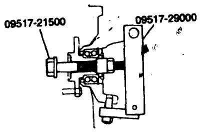
3. Clamp your fist in a vice.
4. Tighten the special tool nut and pull the hub out of the knuckle.
Note: When removing the hub and bearing from the knuckle, replace the wheel bearing assembly (outer and inner rings, cuffs) to a new one.
5. Remove the inner bearing ring from the hub using a special tool.
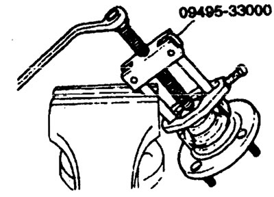
6. Install the bearing inner race that was removed from the hub onto the bearing, and then use the special tool to remove the wheel bearing.
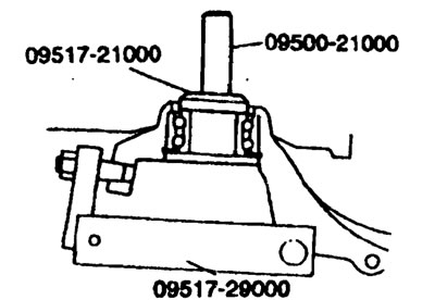
7. Fill the wheel bearing with general purpose grease.
8. Apply a thin coat of general purpose grease to the mating surfaces of the knuckle and bearing.
9. Press the bearing into place using the special tool.
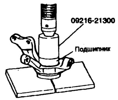
Note: Do not apply pressure to the inner race of the wheel bearing assembly.
10. Install the snap ring into the groove of the knuckle.
11. Install the disc onto the hub and tighten it to the torque specified in the specification.
Tightening torque: 50-60 Nm
12. Using a special tool, mount the hub onto the steering knuckle.
13. Tighten the hub connection to the steering knuckle to a tightening torque of 200-260 Nm using a special tool.
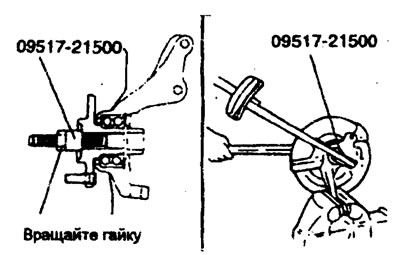
14. Rotate the hub until the bearing is seated.
15. Measure the starting torque at which the hub bearing begins to turn.
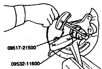
Starting torque of hub bearing is 1.3 Nm or less
16. If the starting torque at which the hub bearing begins to turn is 0 Nm, measure the axial play of the hub bearing.
17. If the axial play of the hub bearing exceeds the limit when tightening the hub nut with a torque of 200-260 Nm, the bearings, hub and steering knuckle are not assembled correctly. Repeat disassembly and assembly.
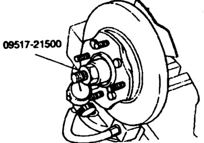
Hub bearing axial play (limit) - 0.08 mm or less
18. Remove the special tool.
Installation
1. Install the parts and tighten them to the torque specified in the specification.
2. Make sure the wheel bearing washer and nut are installed correctly.
3. After installing the wheel, lower the vehicle to the floor and tighten the wheel bearing nut.
4. If the cotter pin holes are not open, tighten the nut to a maximum torque of 260 Nm.
5. Place the cotter pin into the first holes that open and spread its ends.