
Contents: Checking the lamps ⇓ Checking Electric Motors ⇓ Checking switches ⇓ Checking lamp switches and electric…⇓ Checking the sensor switches (alarms) ⇓ Checking the relay ⇓ Checking the windshield wiper motor ⇓ Checking the turn signal flasher ⇓ Checking the brake light ⇓ Checking the rear window defroster ⇓
The main components of a 12-volt electrical system with a grounded "minus" are a 12-volt battery, a generator (crankshaft pulley driven) and starter.
The battery supplies current to the ignition system, lighting devices and other electrical consumers and has a reserve capacity in case the consumed current exceeds the current coming from the generator.
The generator has its own regulator, which provides high output power if the battery is weakly charged and the current consumption is high, and low output power if the battery is fully charged and the current consumption is low.
When connecting electrical components to the vehicle's on-board network with a grounded "minus", it is very important to connect them correctly if they contain silicon diodes or transistors, since if connected incorrectly, these components may fail. This applies to radios, tape recorders, electronic ignition systems, electronic tachometers, electronic corrosion protection devices, etc. - all of them must be connected in the correct polarity.
It is important to know that the positive battery cable must always be disconnected if the battery is being charged in the vehicle. If welding work is carried out using electric welding, the generator must also be switched off to avoid serious damage. Always check that the battery terminals are properly connected to the appropriate wires. When working with electrical equipment, it is recommended to disconnect the negative cable from the battery.
Checking the lamps
After removing the lamp, inspect it. If the filament burns out or the glass bulb is loose on the base, replace the lamp.
Accurate lamp check: connect the lamp via wires to the battery. In this case, polarity is not important. If the lamp does not light, replace the lamp. Check for corrosion on the wire contacts and on the lamp socket. Clean the contacts.
The test lead must be connected to a reliable ground (bare metal) or to the negative terminal of the battery. Hold the test needle of the probe (+) on the current-carrying contact of the connector or pierce the current-carrying wire with it. If at this time the tester lights up, but the lamp does not light, then there is a break in the lamp ground wire. To check this, connect the ground using an auxiliary wire to the lamp socket. The lamp should light up.
Lamps that only have current-carrying wiring are connected to the vehicle ground directly through their housing.
If there is no voltage in the lamp's current-supply wire (the tester does not light up) the switch may fail. Check the switch.
Checking Electric Motors
Electric motors perform many functions in a car:
Check or replace the electric motor fuse.
The electric motors of the electric window and sunroof have automatic fuses that switch off due to overloads and switch on after a while. The deviation may be caused by frozen glass or dirty window guides.
If the fuse blows again, it indicates a short circuit.
To accurately determine the motor defect, connect the motor with two wires of about 2 mm in diameter to the battery. Positive wire to positive terminal, negative wire to negative terminal of motor. If the engine runs well, then the fault was in the power supply. Slow and intermittent rotation of the motor indicates worn carbon brushes. Replace the brushes.
If the motor is running, determine (according to the electrical diagram) the wire that supplies power when the switch is turned on and before the ignition is turned on.
Check the power supply wire. As a tester, you can use a regular incandescent lamp, with a sharp needle at the end of the wire that can be used to pierce the wire.
If there is no voltage at the motor terminals, there is a defect in the power supply. Identify the defect using the electrical diagram and eliminate it. The motors are often switched on via an intermediate relay, so the relay should be checked.
Finally, check the switch.
If the wire is damaged, it is better to lay a new wire.
Checking switches
The function of switches is to close or open an electrical circuit. Some electrical consumers are switched on and off manually. There are switches that work automatically. There are switches that switch the ground wire and switches that cut off the power supply current.
Checking lamp switches and electric motors
For switches with multiple terminals, refer to the electrical diagram to determine which terminal should have voltage.
Check the voltage supply to the switch with a tester. If the lamp lights up, turn on the switch and check for voltage at the output terminal. If there is voltage, the switch is working.
The absence of voltage at the input terminal indicates a break in the current-supplying wire. Check the electrical circuit diagram for voltage supply and install new wire if necessary.
Checking the sensor switches (alarms)
Switch sensors include, for example, oil pressure sensors and coolant or brake fluid level sensors.
Connect a tester or ohmmeter to the sensor terminals, removing the wires from them. V sensors are fixed to the engine block, the sensor body serves as the ground pole.
When the switch is closed, the device should indicate a short circuit. When the switch is closed, the ohmmeter should show 0 Ohms; when open, it should show infinity.
It is more convenient to check the serviceability of the coolant and brake fluid level switches by removing the wire from the switch with the ignition on and connecting it to ground, for example, on the engine block. The indicator light on the dashboard indicates a faulty switch.
When the engine is not running, the oil pressure sensor contact is closed (the control lamp is on), the switch opens only at a certain pressure.
Checking the relay
In cars, relays operate in many electrical circuits: intermediate relays, functional relays and warning signal relays, etc.
Checking the on-relay
When the electrical consumer is turned on, the operating current flows to it through the relay.
The easiest way to check a relay is to replace it with a known good one. But there is not always an extra relay, so the following method is suggested for the relay for switching on and fog lights.
Remove the relay from the socket.
Turn on the ignition and the corresponding switch.
Use a tester to check for voltage on the positive terminal. When the tester lamp lights up, it means that voltage is present. Otherwise, look for a break in the electrical circuit between the battery and the terminal.
Make a jumper from an insulated wire, strip the ends, connect the jumper on the relay block from the positive terminal of the battery to the output contact of the relay, which achieves the effect as if a replacement was made with a known good relay. The location of the terminals on the relay block is determined by the color of the wires or by the electrical diagram.
If the high beam headlights light up with the jumper, the relay is faulty.
If the high beam fails, check the headlight ground connection. Then, using the electrical diagram, find and fix the broken wire.
Install a new relay if necessary.
Checking the windshield wiper motor
The windshield wiper motor is located in the water collection compartment under the windshield, the rear window wiper is in the tailgate. To check, it is necessary to remove the corresponding casing.
Typical Windshield Wiper Test
To determine if the wiper motor or power supply is faulty, follow these steps:
Remove the windshield wiper motor connector.
Connect the battery (+) terminal to terminal 1 using an auxiliary wire. (The engine's negative terminal is already connected to the battery (-) terminal through the body.)
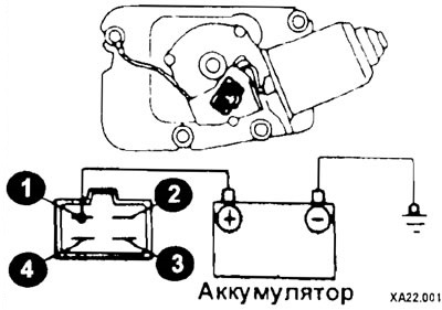
The windshield wiper motor should run slowly. Otherwise, it is a failure of either the motor or stage 1 of the switch.
By connecting the positive wire together with terminal 1 to terminal 2 on the right, the wiper motor should operate at speed II.
Using short connections, start the motor from any position except the end position.
Jumper terminals 1 and 3.
Connect the positive battery terminal to terminal 4 and check that the engine stops at the end position after it starts.
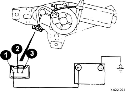
Typical Rear Windshield Wiper Test
Connect the positive battery voltage to contact 1 of the connector and check if the PI motor is working. Then, by short-circuiting contacts 2 and 3, connect the positive battery voltage to contact 1. The motor should start and stop at the end position.
If the motor does not operate correctly, install a new one.
Checking the turn signal flasher
The vehicle's hazard warning lights and direction indicators are protected by different fuses.
If the blinking rhythm on different sides is uneven, it should be assumed that one of the lamps on the "fast" side is defective or there is a broken wire.
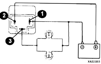
The cause of other faults lies in the circuit breaker relay. To check, remove the turnip. Using auxiliary wires, connect relay contacts 1 and 2 to the battery, and connect two incandescent lamps for the direction indicators, connected in parallel, to contacts 1 and 2. The lights should flash at a rate of 60 to 120 times per minute. Replace the breaker if this condition is not met.
If you don't have a new relay, you can insert a thin wire between contacts 2 and 3 in the relay connector. Bend the ends of the wire before inserting. Reinsert the defective rep
Turn on the ignition. When you switch the turn signal switch, the turn signal lights now light continuously. By rapidly switching the switch on and off, the operation of a circuit breaker can be simulated. But this is a temporary replacement.
If the direction indicators do not light up even with the jumper, then the cause of the malfunction should be sought in the switch or in the wiring.
Checking the brake light
Check the fuse in the fuse box.
If the fuse is faulty, check or replace the brake light bulb.
If the brake light bulbs are not damaged, check the brake light switch, which is located on the bracket above the brake pedal. When you press the pedal, a push pin comes out of the switch. The switch contact closes and the brake light comes on.
To check the brake light switch, disconnect the two cable connectors from it.
Turn on the ignition.
If the brake light comes on when both contacts of the connector are shorted with a jumper, then the brake light switch is faulty and must be replaced.
Checking the rear window defroster
If the rear window defroster does not operate properly, check the fuse in the fuse box.
If the fuse is working properly, check the connector near the rear window; there should be no corrosion on the connector.
If the rear window defroster still does not work, check the switch and wiring.
Check the operation of the on-off relay.
If the heating element breaks, silver conductive paint ("silver paint") can be used to restore the connection.