
Battery
| Type | MF45A4 | MF55A4 | MF68A4 |
| Amp hours (5HR) | More than 36 Ah | More than 44 Ah | More than 54 Ah |
| Current strength when turning the crankshaft of a cold engine | 410A | 500 A | 600 A |
| Reserve capacity | 80 min | 85 min | 110 min |
| Electrolyte density at 25°C, g/cm³ | 1,280±0,01 | 1,280±0,01 | 1,280±0,01 |
Note: Cold Cranking Current is the current that the Battery can deliver for 30 seconds while maintaining a voltage of at least 7.2 V.
Reserve capacity is the time during which the battery can deliver a current of 25 A at a temperature of 26.7°C, while maintaining a voltage of at least 10.5 V.
Starter
| Name | All engines |
| Type | With planetary gear |
| Nominal voltage, V | 12 |
| Nominal power, kW | 0,9 |
| Switch-on time, s | 30 |
| Idle characteristics | |
| Minimum voltage, V | 11,5 |
| Current consumption, A | 60 |
| Rotation speed, min⁻¹ | 5500 |
| Number of gear teeth | 8 |
| Gear clearance, mm | 0,5–2 |
Generator
| Name | Engines 1.3 SOHC n1.5/1.6DOHC | Engines 1.1 SOHC |
| Type | With battery voltage monitoring system | |
| Nominal power | 13.5V/90A | 13.5V/70A |
| Voltage regulator type | Electronic built-in | Electronic built-in |
| Voltage regulator | 14.55±0.2 V | 14.7±0.3 V |
| Temperature compensation | -10±З mV/°C | -10±З mV/°C |
Control and warning lights
| Lamps | Power, W | Color |
| Lighting | 3,4/1,4 | green |
| High beam | 1,4 | blue |
| Low fuel level | 1,4 | amber |
| Turn signal | 1,4 | green |
| Charging the battery | 1,4 | red |
| Oil pressure | 1,4 | red |
| Airbag | 1,4 | red |
| Parking brake | 1,4 | red |
| Seat belt | 1,4 | red |
| Monitoring the operation of engine systems | 1,4 | amber |
| ABS | 1,4 | amber |
| Unclosed door | 1,4 | red |
| The trunk door is open | 1,4 | amber |
| Immobilizer | 1,4 | amber |
| EPS | 1,4 | red |
| O/D switch - automatic transmission mode | 1,4 | amber |
Lighting system lamps
| Lamps | Power, W |
| Headlight | 60/55 (far/near) |
| Front turn signal | 21 |
| Front side marker light | 5 |
| Front fog lights | 27 |
| Rear lights: - rear side lights/brake lights - reverse — turn signal | 5/21 |
| Luggage compartment light | 5 |
| Interior lighting | 10 |
| Directional light lamps in the cabin | 10x2 |
| Rear fog lights | 21 |
| Upper stack signal | 16 |
| Interior lighting that turns on when the door is opened | 5 |
| License plate lighting | 5x2 |
Windscreen wiper and washer
| Name | Technical requirements | |
| Windshield wiper motor | Insulation resistance, mOhm | not less than 1.0 |
| Speed/current, 1.0 Nm | Slow: 44–52 min⁻¹/ no more than 3.5 A Fast: 64–78 min⁻¹/ no more than 4.5 A | |
| Speed/current, 4.0 Nm | Slow: 39-47 min⁻¹/ no more than 5.5 A Fast: 56–68 min⁻¹/ no more than 7 A | |
| Current when blocking | Slow: no more than 24 A Fast: no more than 28 A | |
| Rear window wiper motor | Speed/current, no load | 38–50 min"1/ no more than 2.0 A |
| Speed/current, 1.0 Nm | 35–45 min~1/ no more than 3.5 A | |
| Current when blocking | no more than 14 A | |
| Steering angle without load | 173±3° | |
| Washer pump capacity, ci | m³/min | 1500 |
| Pressure generated by the pump, kg/cm² | 1,8 | |
| Uninterrupted operation, with | With water | 60 |
| Without water | 20 |
Speedometer
| Speed, km/h | 20 | 40 | 60 | 80 | 100 |
| Tolerance, km/h | 20–24,6 | 40–44 | 60,8–65,4 | 81,4–86,8 | 102,5–108,2 |
| Speed, km/h | 120 | 140 | 160 | 180 | 200 |
| Tolerance, km/h | 123,5 -129,6 | 144,4–151 | 165,4–172,4 | 186,3–193,8 | 207,2–215,2 |
Tachometer
| Frequency, min⁻¹ | 1000 | 2000 | 3000 | 4000 | 5000 | 6000 |
| Tolerance, min⁻¹ | ±100 | ±125 | ±150 | ±170 | ±180 | ±210 |
Tightening torques, Nm
| Terminal (B+) of the generator | 5–7 | ||||||
| Terminal (B+) of the starter | 10–12 | ||||||
| Battery terminals | 4–6 | ||||||
| Spark plug | 20–30 | ||||||
General information
The negative ground electrical system has an operating voltage of 12 volts. Power for the electrical system comes from a lead-acid battery, which is recharged by the generator.
It should be noted that when working with any element of the vehicle's electrical equipment, the negative battery terminal wire must be disconnected to prevent short circuits and/or fire.
Check the placement and fastening of the wires at regular intervals, making sure that the wires do not rub against other elements. If you find that any wires are rubbing against other elements, move the wires to the side and secure them so that this does not happen again.
Precautionary measures
It is prohibited to change the polarity of the power supply of various devices and electrical equipment in order to avoid failure of semiconductor devices.
Do not disconnect or connect the battery, measuring instruments or any wires while the engine is running.
It is prohibited to check the generator's serviceability by short-circuiting the power terminal to ground.
Diagnostics of faults of on-board electrical equipment
A typical electrical circuit may include a main electrical component, various switches, relays, electric motors, fuses, fuse links, or circuit breakers related to the component, and wiring and connectors used to connect the main component to the battery and body ground. To help troubleshoot electrical circuits, the manual includes electrical schematics and wiring diagrams.
Before you begin troubleshooting any electrical circuit, carefully study the relevant diagram to get a clearer idea of its functional purpose. The troubleshooting circle is usually narrowed by gradually identifying and eliminating normally functioning elements of the same circuit. If several elements or circuits fail at the same time, the most likely cause of the failure is a blown fuse or a ground fault (different circuits can often be shorted to the same fuse or ground terminal).
Electrical equipment failures are often due to simple causes such as corroded connector contacts, a blown fuse, a blown fuse link, or a damaged relay. Visually inspect all fuses, wiring, and connectors in a circuit before attempting more specific component checks.
When using diagnostic tools to troubleshoot a fault, carefully plan (in accordance with the attached electrical diagrams) where in the circuit the tool should be connected and in what sequence in order to most effectively identify the fault.
Basic diagnostic tools include an electrical circuit tester or voltmeter (a 12-volt test lamp with a set of connecting wires can also be used), a circuit breaker indicator (probe) that includes a lamp, its own power source and a set of connecting wires. In addition, you should always have a set of jumper cables (another car's battery) in the car, equipped with crocodile clips and preferably an electrical circuit breaker, which can be used to bypass and connect various electrical components when diagnosing the circuit. As already mentioned, before you start checking the circuit with diagnostic equipment, determine from the diagrams where it is connected.
Checks for the presence of supply voltage are carried out in the event of a fault in the electrical circuit. Connect one of the tester leads to either the negative battery terminal or a well-grounded point on the vehicle body. Connect the other tester lead to the terminal of the connector of the circuit being tested, preferably the one closest to the battery or fuse. If the tester indicator lamp lights, there is power supply voltage on that section of the circuit, which confirms that the circuit between that point in the circuit and the battery is OK. Proceed in the same manner to test the rest of the circuit. If there is a power supply voltage fault, there is a fault between that point in the circuit and the last one tested previously (where there was power supply voltage). In most cases, the cause of the failure is loose connector contacts and damage to the contacts themselves (oxidation).
Caution: Remember that some on-board electrical circuits are only powered when the ignition key is in the ACC (park) or RUN (drive) position.
Searching for the location of the short circuit. One method of finding a short circuit is to remove the fuse and connect a test lamp or voltmeter instead. There should be no voltage in the circuit. Pull the wiring while watching the test lamp. If the lamp starts to blink, there is a short to ground somewhere in the wiring harness, possibly caused by chafing of the wire insulation. A similar check can be carried out for each component of the electrical circuit by turning on the corresponding switches.
Checking the grounding serviceability. This test is performed to determine the reliability of the grounding of the circuit element. Disconnect the battery and connect one of the wires of the test lamp, which has an independent power source, to a known good ground point. Connect the other wire of the lamp to the wire harness or connector contact being tested. If the lamp lights up, the grounding is OK (and vice versa).
A break test is performed to detect breaks in an electrical circuit. After disconnecting the power supply to the circuit, test it with a test lamp with an independent power source. Connect the test leads to both ends of the circuit. If the test lamp lights up, there is no break in the circuit. If the lamp does not light up, this indicates that there is a break in the circuit. In a similar way, you can check the serviceability of the switch by connecting the test lamp to its contacts. When you move the switch to the "On" position, the test lamp should light up.
Localization of the break point. When diagnosing a suspected open circuit section, it is quite difficult to visually detect the cause of the malfunction, since inspecting the terminals for corrosion or poor contact quality is difficult due to limited access to them (usually the terminals are covered by the connector housing). A sharp jerk of the connector housing on the sensor or its wire harness in many cases leads to contact restoration. Do not forget about this when trying to localize the cause of failure of a suspected open circuit. Unstable failures may be due to oxidation of the terminals or poor contact quality.
Diagnosing electrical circuit faults is not a difficult task, provided that you clearly understand that electric current flows to all consumers (lamp, electric motor, etc.) from the battery via wires through switches, relays, fuses, fuse links, and then returns to the battery through the car body "ground". Any problems associated with the failure of electrical equipment can be caused by the cessation of the supply of electric current to them from the battery or the return of current to the battery.
Wires, Fuses and Relays
Protection of the car's electrical circuits from short circuits is provided by the use of fuses, circuit breakers and fusible links. A burnt-out fuse can be easily distinguished from a working one by examining its transparent plastic housing. Carefully inspect the fuse. If the fuse looks normal on the outside, but you still suspect that it is faulty, check the conductivity between the blade-type contacts protruding from its housing.
When replacing fuses, make sure that the rating of the new fuse matches the rating of the old one. Fuses rated for different currents may look the same, so pay special attention to the markings. Replacing a blown fuse with one rated for a lower, and especially higher, current is not advisable. Each electrical circuit requires a different degree of protection. Make sure that the markings on the fuse body correspond to the current for which it is rated
the corresponding circuit. If the replaced fuse immediately burns out, it is not wise to continue replacing it. First of all, you should determine and eliminate the cause of its burnout. In most cases, this is a short circuit in the electrical circuit caused by a break or damage to the wire insulation.
Fusible links
Some electrical circuits are protected by the inclusion of fuse links. Links are usually used to protect circuits that are not equipped with fuses, such as the ignition circuit.
Fuse links are similar to fuses in that their failure (melting) is easily determined visually.
To replace the fuse link, disconnect the wire from the negative terminal of the battery. Remove the burnt link and install a new one in its place. Before replacing the link, be sure to try to determine the cause of the overload that caused the link to fail.
Circuit breakers (thermal relays)
Thermal relays are used to protect such elements as electric window lifters, door locks and electric correctors. Some of the circuit breakers are installed in the mounting block. The return of thermal relays to the initial state on some models is carried out automatically, i.e. when an overload occurs in the circuit, the thermal relay immediately opens, then after cooling, returns to the initial state. If the circuit does not return to the working position, it should be checked immediately. Normal operation of the thermal relay confirms the serviceability of the circuit. Some of the breakers are equipped with buttons for forced manual return to the initial state.
Replacing fuses
To prevent short circuits and overloads of electrical consumers, individual circuits are protected by fuses. Hyundai vehicles use blade-type fuses that comply with the latest technical achievements.
Before replacing a fuse, be sure to first disconnect the corresponding consumer.
Use a narrow screwdriver to pry the fuse box cover off.
A blown fuse is identified by a melted metal strip. The location of the fuses is shown on the inside of the fuse box cover.
Remove the faulty fuse using the plastic tweezers located in the fuse box cover.
Insert a new fuse of the same rating (amperage).
If a newly inserted fuse blows after a short time, check the corresponding electrical circuit.
Never replace a fuse with wire or similar auxiliary means ("bugs"), as this may cause serious damage to the vehicle's electrical system.
It is recommended to always have a set of spare fuses of different ratings in the car. There is a special place for storing them in the fuse box.
The current strength for which the fuse is designed is marked on the back of its housing. In addition, the housing is painted in a corresponding color, by which the rated current strength can be determined (Table 7.1).
Close the fuse box cover.
Correspondence of fuse color to rated current
| Nominal current, A | Color |
| 5 | Beige |
| 10 | Red |
| 15 | Blue |
| 20 | Yellow |
| 25 | Colorless |
| 30 | Green |
Purpose of fuses under the hood
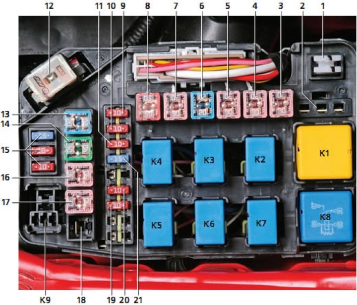
| Designation | Item number in the photo | Nominal current, A | Protected consumer circuits |
| Ef1 | 3 | 30 | Ignition switch, starter relay |
| Ef2 | 4 | 30 | Ignition switch, instrument cluster indicator lights |
| Ef3 | 5 | 30 | Engine Management System Main Relay, Generator Pre-Excitation Circuit, ECU |
| Ef4 | b | 20 | Fuel cut-off switch |
| Ef5 | 7 | 30 | Low and high speed relay for the electric fan of the engine cooling system |
| Ef6 | 8 | 50 | Electric door locks, hazard warning lights, brake lights, side lights, heated rear window, instrument cluster and panel lighting, interior lighting, audible door open warning light |
| Ef7 | 9 | 10 | ABS block |
| Ef8 | 10 | 10 | ECU |
| Ef9 | 11 | 10 | ECU, fuel pump relay, air conditioner relay, oxygen concentration sensor |
| Ef10 | 21 | 15 | ECU, injectors, camshaft position sensor, crankshaft position sensor, idle speed control valve, purge solenoid valve of the adsorber |
| Ef11 | 19 | 10 | Air Conditioning Compressor Relay |
| Ef 12 | 20 | 10 | Horn relay |
| Ef13 | 13 | 20 | ABS block |
| Ef 14 | 14 | 40 | ABS block |
| Ef 15 | 16 | 30 | Heater fan electric motor |
| Ef 16 | 17 | 30 | Electric windows |
| Ef 17 | 18 | 50 | Electric power steering (on a car with a 1.6L engine) |
| Ef 18 | 12 | 120 | Charging the battery |
| Ef 19 | 15 |
Purpose of fuses located in the passenger compartment
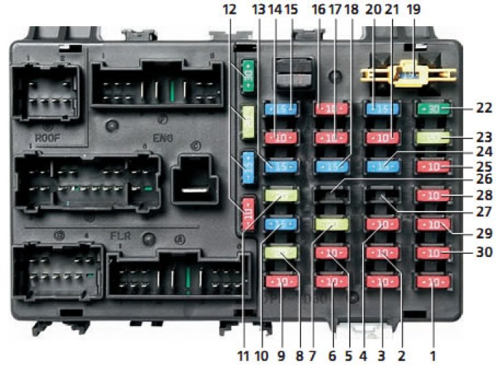
| Designation | Item number in the photo | Nominal current, A | Protected consumer circuits |
| F1 | 1 | 10 | Air conditioner switch |
| F2 | 3 | 10 | Left side marker lights of the car |
| F3 | 6 | 10 | Airbag |
| F4 | 9 | 10 | Audio system, electric drive for outside rear view mirrors |
| F5 | ZS | 10 | Automatic transmission gear selector switch, reverse light switch |
| F6 | 2 | 10 | Starboard side marker lamps, license plate lights, open door sound indicator |
| F7 | 5 | 10 | Instrument cluster warning lights, seat belt reminder timer, alarm control unit |
| F8 | 8 | 20 | Cigarette lighter |
| F9 | 29 | 10 | ECU, generator, electric power steering control unit, ABS wheel speed sensors, automatic transmission overdrive lock switch |
| F10 | 4 | 10 | Airbag control unit |
| F11 | 7 | 20 | Door locking system |
| F12 | 10 | 15 | Rear door glass wiper motor |
| F13 | 28 | 10 | Starter relay, alarm relay |
| F14 | 27 | - | Not used |
| F15 | 26 | - | Not used |
| F16 | 11 | 20 | Front seat heating switch |
| F17 | 25 | 10 | E5U, switch for heating the rear door glass and outside rear-view mirrors (optional) |
| F18 | 24 | 15 | Ignition coils, E5U |
| F19 | 18 | 15 | Brake light switch |
| F20 | 13 | 15 | Hazard warning switch, security alarm unit |
| F21 | 23 | 20 | Windscreen wiper and washer motors |
| F22 | 21 | 10 | Rear fog light relay |
| F23 | 17 | 10 | Fog lamp relay. Window lifter relay, tailgate glass heating timer, left/right headlamp electric drive, headlamp corrector switch |
| F24 | 14 | 10 | Heater Fan Relay |
| F25 | 22 | 30 | Rear door glass heating relay |
| F26 | 20 | 15 | Right headlight bulb |
| F27 | 16 | 10 | Fog light relay |
| F28 | 15 | 15 | Headlight bulb left headlamp |
| F29 | 19 | 15 | Rear fog light switch, audio system, door ajar warning light sensor, diagnostic connector, luggage compartment light, interior light |
| F30 | 12 | 30,20,15,10 | Spare fuses |
Relay
Relays are used to supply electric current to some elements of the car's electrical equipment. A malfunction of a relay leads to the failure of the element it serves. If you suspect a malfunction of any of the relays, check it at a service station or in a specialized auto repair shop. A failed relay is replaced as an assembly.
Installation of additional electrical equipment
When drilling holes in the body, burrs must be removed from their edges, the edges themselves must be primed and painted. The chips formed during drilling must be removed from the body. In all work related to electrical equipment, to avoid short circuits, it is imperative to disconnect the ground cable from the battery.
Caution! When the battery is disconnected, information from the memory of the electronic control unit of the engine and gearbox, the anti-lock braking system and other electrical devices, such as the radio and clock, is erased.
Cables installed during the installation of additional electrical equipment should, if possible, be laid along the wire bundles and secured using cable clamps and rubber bushings.
If required, additionally secure the wires with adhesive tape, cable ties or similar fasteners to prevent electromagnetic noise and friction. It should be noted that there should be a distance of at least 10 mm between the brake pipes and rigidly laid electrical wires, and at least 25 mm between the brake pipes and electrical wires connected to the engine or other vehicle components.
When installing additional electrical equipment, check whether the generator power reserve is sufficient. If necessary, install a generator with more power.