HyundaiBook.ru
Repair Chevrolet Repair Honda Repair Toyota Repair Land Rover Repair VAZ Repair Renault Repair Nissan
English Русский
Български
Беларускі
Український
Српски
Hrvatski
Română
Polski
Slovenský
Magyar
ArticlesSitemapContacts  


  Accent   Elantra   Getz   Grandeur   Sonata   Santa Fe   Tucson   Others
Getz (2002-2011)
  • Main
  • Getz
  • 1 (2002-2011)
  • Electrical equipment
  • Equipment and devices
  • Instrument cluster — removal, installation and testing

Instrument cluster — removal, installation and testing (Hyundai Getz 1)

0
Contents: Removal and installation ⇓ Checking the speedometer ⇓ Tachometer ⇓ Fuel level indicator ⇓ Resistance check ⇓ Temperature indicator ⇓ Temperature sensor ⇓ Oil pressure sensor ⇓

Removal and installation


1. Disconnect the cable from the negative terminal of the battery.

2. Remove the screw and remove the instrument cluster frame.

2. Remove the screw and remove the…


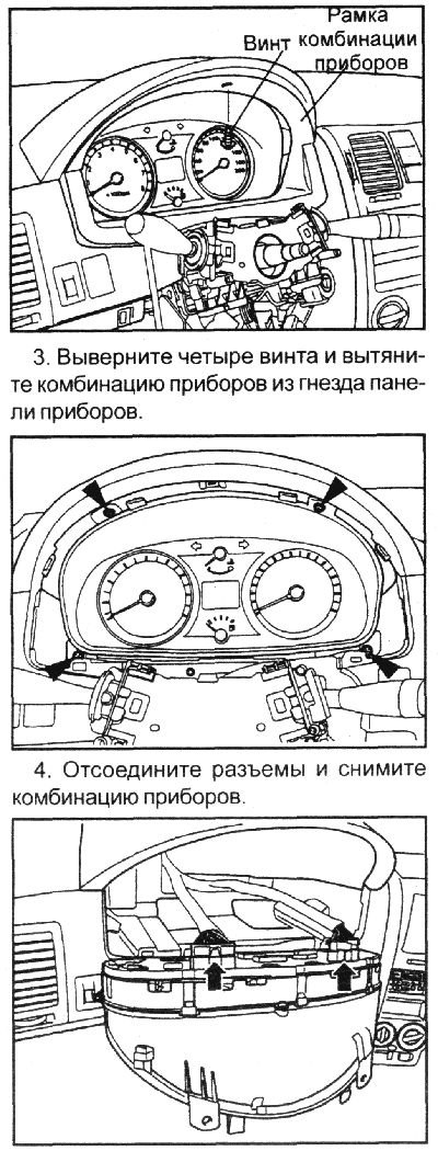
5. Installation is carried out in the reverse order of removal.

5. Installation is carried out in the…


Checking the speedometer


1. Adjust tire pressure.

2. Place the vehicle on a speedometer test stand and place chocks under the rear wheels.

3. Check if the speedometer readings are within the tolerance specified in the technical data.

Caution! When checking the speedometer, do not suddenly press the clutch pedal or increase/decrease the speed sharply.


Note: Tire wear and incorrect tire pressure will increase the speed measurement error.


Tachometer


1. Connect the Scan tool to the diagnostic connector.

2. Start the engine. Compare the vehicle speedometer readings with the test tachometer readings. If the difference in readings exceeds the permissible values, replace the tachometer.

Warning!
  • 1. Reversing the polarity of the tachometer will damage the semiconductor devices inside the tachometer.
  • 2. When removing and installing the tachometer, be careful not to drop or hit it.


Fuel level indicator


1. Disconnect the connector from the fuel level sensor.

2. Connect a 3.4W, 12V lamp to terminals 2 and 3 of the wire portion of the connector.

2. Connect a 3.4W, 12V lamp to…


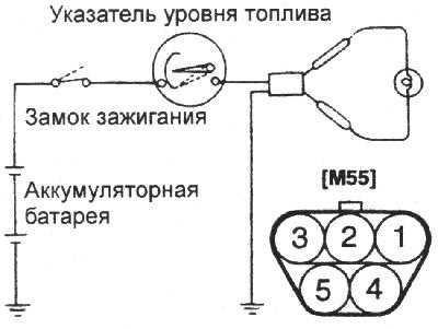
3. Turn on the ignition and make sure that the indicator lamp is fully lit and the indicator arrow shows a full tank.

Resistance check


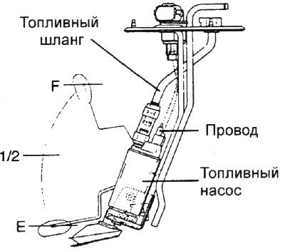
1. Connect a variable resistor to terminals 2 and 3. Check that the gauge shows the fuel level according to the change in resistance. Otherwise, replace the fuel gauge.

Resistance, OhmLevel
110E (Empty)
32,51/2
4,0F (Full)

2. Also make sure that when moving the float from position "E" to position "F", the resistance changes smoothly.


Temperature indicator


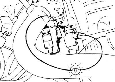
1. In the engine compartment, disconnect the connector from the coolant temperature sensor.

2. Turn on the ignition and make sure that the pointer is in the "cold" position. Turn off the ignition.

3. Connect a 3.4 W, 12 V lamp to the sensor connector terminal and ground.

3. Connect a 3.4 W, 12 V lamp to the…


4. Turn on the ignition.

5. The control lamp should be on and the pointer should be in the "hot" position.

Temperature sensor


1. Use an ohmmeter to measure the resistance between contacts 2 and ground.

2. If the resistance does not match those shown in the table, replace the temperature gauge.

Temperature,°C6085110125
Resistance, Ohm118492514,6

Oil pressure sensor


1. Make sure that there is continuity between the sensor contact and ground when the engine is off.

1. Make sure that there is continuity…


2. Make sure that there is no conductivity between the sensor contact and ground when the engine is running.

3. Otherwise, replace the oil pressure sensor.
This article is available at russian, bulgarian, belarusian, ukrainian, serbian, croatian, romanian, polish, slovak, hungarian
This article has been reviewed by: Konstantin Smirnov
Add to social network:

Previous
Getz: Equipment and devices
Next

Ignition switch — removal, installation and testing
Fuses and their location
Relay in the car interior
Location and testing of relays
Troubleshooting the Windshield Wiper Switch
Control devices — removal, installation and testing
Parking brake position switch
Multifunction switch — removal and installation
Horn — Removal, Installation and Testing
Audio system — removal and installation
We recommend other articles on the topic of Hyundai manuals:

Instrument cluster, type A Hyundai Accent 3 (2005-2010)
Instrument cluster (vehicles without trip computer) Hyundai Elantra 3 (2000-2006)
Instrument cluster indicators Hyundai Sonata 4 (2001-2012, petrol)
Instrument cluster and indicator lights Hyundai Santa Fe 2 (2007-2012, petrol)
Instrument cluster Hyundai Tucson 1 (2005-2010)
Instrument cluster Hyundai Matrix (2001-2010, petrol)

Link in different formats to this article

Visitor comments
No comments yet


How much will 34 + 35 ?


Getz (2002-2011) 
  • User manual
  • Control devices
  • Heating and ventilation
  • Audio system
  • Car driving
  • Faults en route
  • Maintenance
  • Technical information
  • Power unit
  • Engine repair 1.1/1.3 l
  • Engine repair 1.5/1.6 l
  • Lubrication system
  • Cooling system
  • Fuel system
  • Exhaust system
  • Ignition system
  • Transmission
  • Clutch
  • Mechanical gearbox
  • Automatic gearbox
  • Drive shafts and axles
  • Chassis
  • Suspension and wheels
  • Steering
  • Brake system
  • Body
  • Exterior (external elements)
  • Interior (internal elements)
  • Air conditioning and heater
  • Electrical equipment
  • Equipment and devices
  • Power devices
  • Electrical circuits
HyundaiBook.ru © 2018-2026 · Mobile version · Sitemap: EN BG BY UA RS HR RO PL SK HU · Administration · Site search · Hyundai owners Accent 1 · Accent 2 · Accent 3 · Elantra 1 · Elantra 2 · Elantra 3 · Getz · Sonata 3 · Sonata 4 · Santa Fe 2 · Tucson 1 · Tucson 2 · Matrix ·
This site uses cookies to optimize its functionality. By continuing, you agree to our terms.