
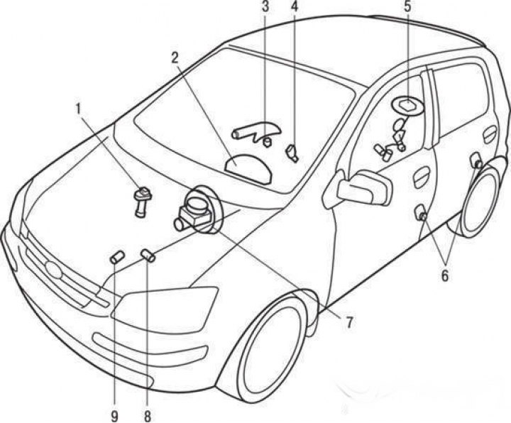
Location of control instrument sensors: 1 – vehicle speed sensor; 2 – instrument cluster; 3 – Parking brake indicator lamp switch; 4 – Seat belt warning light switch; 5 – fuel level indicator and fuel reserve indicator lamp sensor; 6 – door limit switches; 7 – brake fluid level sensor; 8 – oil pressure sensor; 9 – coolant temperature sensor
Instrument cluster
Removal and installation
Disconnect the cable from the negative ("–") terminal of the battery.
Remove the instrument cluster frame by unscrewing the mounting screw.
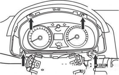
Instrument cluster mounting screws
Remove the instrument cluster from its socket by unscrewing the four mounting screws.
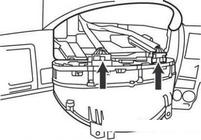
Instrument cluster connectors
Disconnect the instrument cluster connectors.
Installation is carried out in the reverse order of removal.
Checking the technical condition
Speedometer
Checking the correctness of the speedometer readings should be carried out on a special stand in a car service station.
When tires wear out or tire pressure deviates from the norm, the speedometer error increases.
Speedometer reading error
| Speed, km/h | Tolerance, km/h |
| 120 | 123,5-129,6 |
| 140 | 144,4-151,0 |
| 160 | 165,4-172,4 |
| 180 | 186,3-193,8 |
| 200 | 207,2-215,2 |
| 20 | 20,0-24,6 |
| 40 | 40,0-44,0 |
| 60 | 60,8-65,4 |
| 80 | 81,4-86,8 |
| 100 | 102,5-108,2 |
Tachometer
Install and connect the control tachometer in accordance with the operating instructions.
Attention!
- Reversing the polarity when connecting the tachometer can damage its transistor and diodes.
- When removing and installing the tachometer, try not to drop it and protect it from strong impacts.
With the engine running, compare the readings of the control tachometer with the readings of the standard tachometer. If the measurement tolerance limits are exceeded, replace the tachometer.
Tachometer reading error
| Engine crankshaft speed, min⁻¹ | 1000 | 2000 | 3000 | 4000 | 5000 | 6000 | 7000 |
| Tolerance, min⁻¹ | ±100 | ±125 | ±150 | ±150 | ±150 | ±180 | ±210 |
Fuel level indicator
To check the functionality, disconnect the fuel level sensor connector.
Connect a 3.4 W, 12 V test lamp to contacts "2" and "3" of the cable portion of the fuel level sensor connector.
Turn on the ignition and make sure that the indicator lamp lights up and the fuel gauge needle moves to the "F" position (full tank).
Fuel level sensor
Check the resistance between contacts "2" and "3" of the sensor with an ohmmeter at each position of the float ("E" – empty tank; "1/2" - half a tank; "F" - full tank).
Check the smoothness of the resistance change when moving the float from position "E" to position "F".
Resistance between the terminals of the fuel level sensor
| Float position | F (full tank) | 1/2 | E (empty tank) |
| Resistance, Ohm | 4,0 | 32,5 | 110 |
Fuel reserve sensor
Connect a test lamp (12 V, 3.4 W) and a battery in series to the sensor terminals. Immerse the sensor in water.
When the thermistor is immersed in water, the indicator control lamp should not light; when removed from water, it should light.
Note: If faulty, replace the fuel level sensor assembly.
Caution: After completing this check, wipe the sensor dry and install it in the fuel tank.
Coolant temperature gauge
In the engine compartment, disconnect the connector from the coolant temperature sensor.
Turn on the ignition and make sure that the coolant temperature gauge needle is in the "cold" position.
Turn off the ignition.
Connect a test lamp (12 V operating voltage and 3.4 W power) to the contact of the cable part of the sensor connector and to the ground.
Turn on the ignition. The indicator lamp should be on and the pointer should be in the "hot" position.
If the test result is not as specified above, replace the temperature gauge, then test the system again.
Coolant temperature sensor
Use an ohmmeter to check the resistance between contact "2" of the sensor and ground.
If the resistance does not match the value specified in the table, replace the sensor.
Resistance between the coolant temperature sensor contact and ground at different temperature values
| Temperature,°C | 60 | 85 | 110 | 125 |
| Resistance, Ohm | 118 | 49,0 | 25,0 | 14,6 |
Oil pressure sensor
With the engine not running, check for continuity between the oil pressure sensor terminal and ground.
With the engine running, make sure there is no circuit between the sensor contact and ground.
If the test result is not as specified above, replace the sensor.
Oil pressure warning light
Disconnect the contact connector from the oil pressure sensor and connect the contact of the sensor wire to ground.
Turn on the ignition and make sure the indicator lamp lights up. If the lamp does not light up, check the lamp and wires.
Brake fluid level sensor
Disconnect the sensor connector located on the brake fluid reservoir.
By pressing down on the sensor (float) with some rod, make sure that there is a circuit between contacts "1" and "2" of the sensor.
Brake fluid level indicator light
Start the engine. Release the parking brake.
Disconnect the brake fluid level sensor connector.
Connect the contacts of the cable part of the sensor connector to ground.
Make sure the indicator light comes on.
Parking brake warning light switch
The push-type parking brake indicator switch (limit switch) is located under the parking brake lever. To adjust the switch position, move the switch bracket up or down with the parking brake actuator lever set to the lowest position.
Check for the presence of a circuit between the terminal and the switch housing when the switch contacts are closed (with the parking brake system drive lever in the upper position).
Make sure that there is no circuit between the terminal and the switch housing when the switch contacts are opened (with the parking brake lever lowered).
If the test results do not match those specified above, replace the switch or check its connection to ground.
Safety belt warning light switch
Disconnect the switch contact connector.
Check for continuity between the switch contacts.
With the seat belt fastened, the resistance should be equal to infinity.
When the seat belt is not fastened, the resistance should be zero.
Seat belt reminder light
With the ignition on, check the operation of the indicator lamp.
When the seat belt is fastened, the indicator lamp should not light.
When the seat belt is not fastened, the indicator lamp should light.