
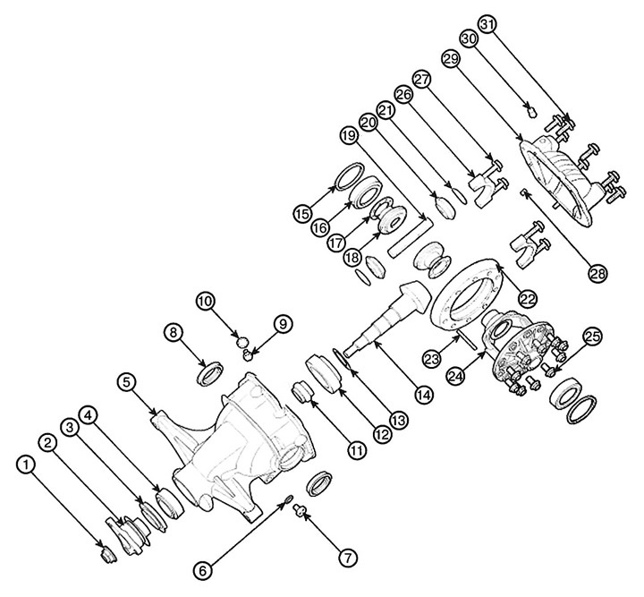
1. Pinion nut
2. Connecting flange
3. Front oil seal
4. Front drive pinion bearing
5. Main gear housing
6. Gasket
7. Filler plug
8. Lateral seal
9. Drain plug
10. Gasket
11. Drive gear bearing adjusting shim (flexible shim)
12. Rear bearing of drive pinion
13. Drive gear height adjustment gasket
14. Drive gear
15. Side bearing adjusting washer
16. Side bearing
17. Thrust washer of the axle gear
18. Half-axle gear
19. Axle of satellites
20. Satellite
21. Satellite thrust washer
22. Drive gear (toothed rim)
23. Locking pin
24. Differential housing
25. Ring gear bolt
26. Bearing cover
27. Bearing cap bolt
28. Dowel pin
29. Back cover
30. Sapun
31. Cover bolt
Replacement
1. Drain the oil from the final drive housing.
2. Remove the rear drive shaft.
3. Remove the driveshaft.
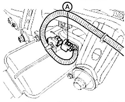
4. Disconnect the clutch control connector (A).
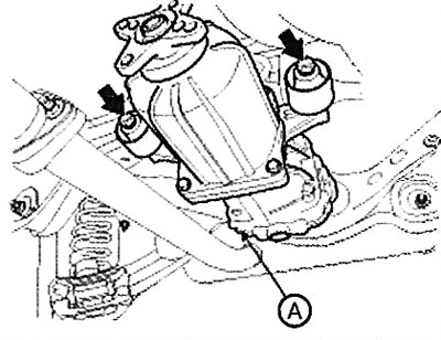
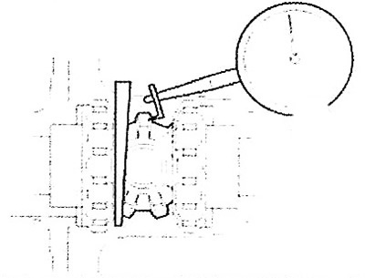
5. Support the final drive assembly (A) with a jack (B).
Note: Tightening torque: 68.6 - 88.3 Nm.
 |
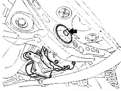 |
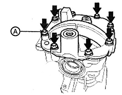
6. Loosen the mounting bolt and remove the cover (A) of the main gear.
Note: Tightening torque: 39.2 - 49.0 Nm.
7. Installation is carried out in the reverse order of removal.
Checking the technical condition
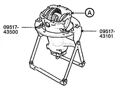
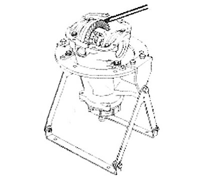
Install the final drive housing (A) using the special tools (09517-43101 and 09517-43500). Then perform the following check.
1. Check the play in the final drive as follows.
(1) Fix the drive gear and turn the driven gear to check whether the backlash is within the standard value.
Note:
Take measurements at 4 points around the circumference of the drive gear.
Standard value: 0.10 - 0.15 mm.
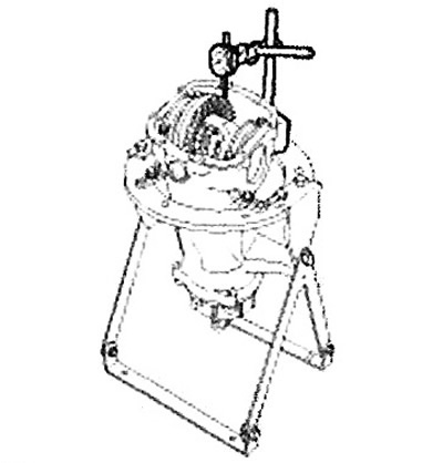
2. Check the runout of the back side of the driven gear as follows.
(1) Place a dial indicator on the reverse side of the driven gear and measure the runout.
Note: The maximum permissible value is 0.05 mm.
(2) If the runout is outside these limits, check that there are no foreign objects between the driven gear and the final drive case and that the driven gear mounting bolts are properly tightened.
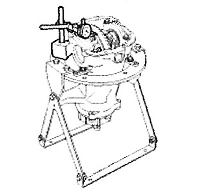
3. Check the differential gear play as follows,
(1) Fix the axle gear with a wedge so that it cannot move, and measure the backlash of the differential driven gear with a dial indicator installed on the drive gear.
Note: Standard value: 0 - 0.05mm.
The text is taken from an online source HYUNDAIBOOK.RU
Take measurements at two points on the pinion gear.
(2) If the play exceeds the limit value, adjust the engagement using the axle bearing adjusting washers.
Note: If adjustment is not possible, replace the axle gear and pinion gear as a set.
4. Check the shape of the contact patch in the final drive as follows.
(1) Apply an equal amount of paint to both surfaces of the driven gear tooth.
(2) Insert a copper rod between the final drive case and the differential case, and then turn the propeller shaft mounting flange by hand (once in one direction, then once in the other direction), applying such a load to the driven gear that the load on the pinion gear is approximately 25 - 30 Nm.
Caution: If the rotation angle is too large, the contact patch in the engagement will become unclear and its shape will be difficult to check.
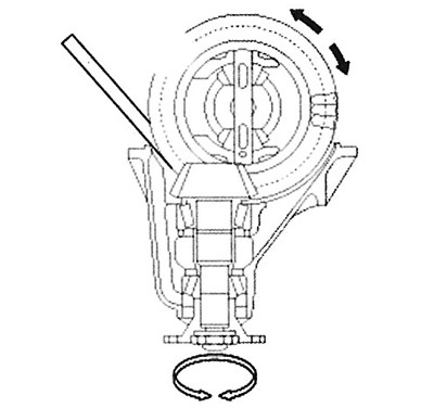
(3) Check the shape of the contact patch in the engagement.
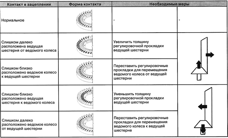
Note:
After each adjustment of the contact patch, it is necessary to measure the gap in the engagement of the teeth.
If the contact patch cannot be adjusted, the final drive assembly must be replaced.
5. Check for oil leaks and the seal lip for damage or wear.
6. Check the bearings for wear or discoloration.
7. Check the final drive housing for cracks.
8. Check the drive and driven gears for wear or cracks.
9. Check the axle gears, pinion gear and pinion shaft for wear or damage.
10. Check the axle gear splines for wear and damage.