
Removal
1. Remove the front wheel.
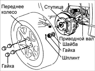
2. Remove the cotter pin from the drive shaft, unscrew the nut and remove the washer securing the shaft to the front wheel hub.
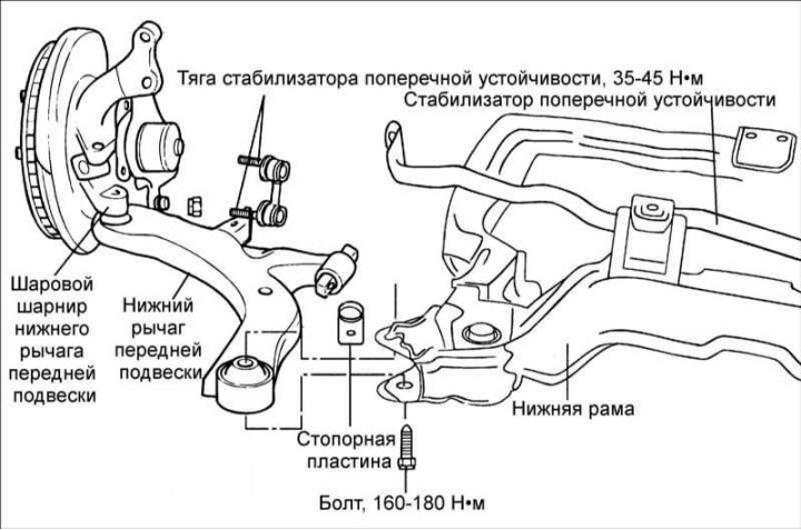
3. Loosen the lower arm ball joint mounting nut, but do not unscrew it completely.
4. Remove the two bolts securing the lower part of the strut to the steering knuckle.
5. By pushing the steering knuckle outward, remove the drive shaft from the hub.
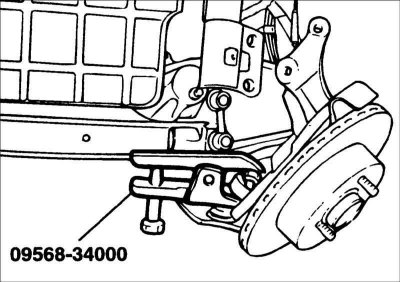
6. Using puller 09568–34000, press the ball joint pin out of the steering knuckle.
7. Temporarily install the lower front suspension strut mounting bolt.
8. Unscrew the stabilizer link mounting nut.
9. Remove the lower arm bushing (A) and (G) mounting bolts.
10. Remove the lower arm.
Disassembly
Replacing the ball joint and dust cover
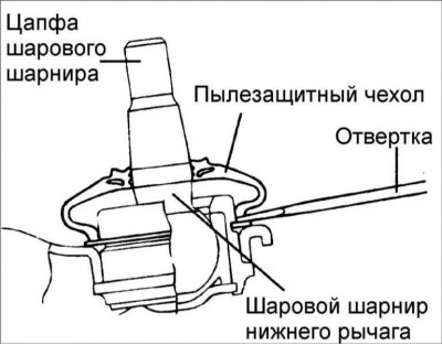
1. Using a screwdriver blade, remove the dust cover from the lower arm ball joint.
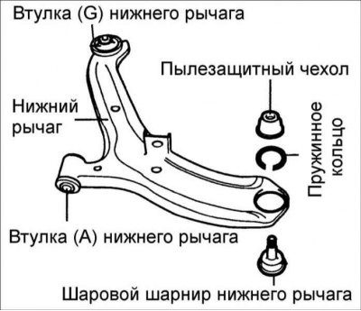
2. Remove the snap ring.
Information is taken from a thematic website [HyundaiBook]
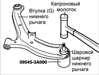
3. Use a nylon hammer to separate the ball joint from the lower arm.
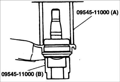
4. Using special tool 09545–11000, press the new ball joint into the lower arm.
5. Install the snap ring.
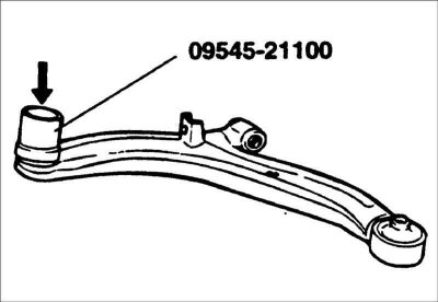
6. Using special tool 09545 – 21100, install the dust cover.
Replacing the bushing (G) of the lower arm
1. Install special tools 09545-02000, 09216-21200 and 09216-21200 to the lower arm.
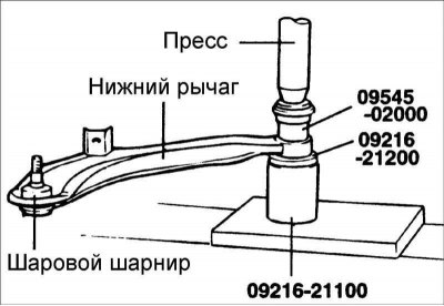
2. Remove the bushing.
3. Lubricate the following parts with soapy water:
- the outer surface of the new bushing;
- inner surface of the lower arm bushing mount.
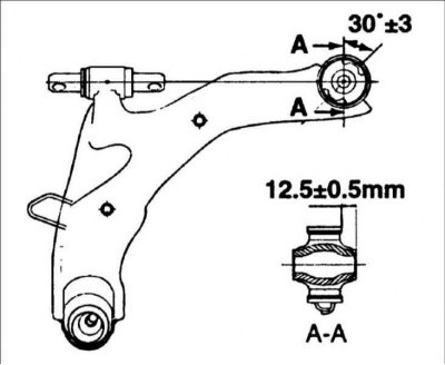
4. Using special tool 09216–21100, 09624–34000, install the new bushing onto the lower arm.
Caution: Press in the bushing (G) so that it is in the position shown in the figure.
Caution: After installing the bushing, wipe off the soap solution. Pressing force: 80 N.
Examination
1. Check the bushing for wear and deterioration.
2. Check the lower arm for bending or damage.
3. Check the ball joint protective boot for cracks.
4. Check the condition of all bolts.
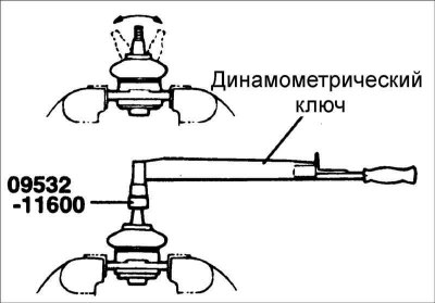
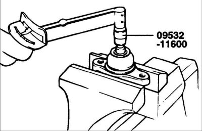
5. Check the torque required to turn the lower arm ball joint journal.
- If there are cracks in the protective boot, replace the ball joint.
- Rock the lower arm ball joint pin from side to side several times.
- Measure the torque required to turn the lower control arm ball joint pin. Torque: 3.5–10 Nm
- If the torque exceeds the permissible values, replace the ball joint.
- If the torque is significantly below the permissible value, the ball joint can be used repeatedly as long as it does not jam or have excessive play.
Installation
1. First, install the lower arm bushing (G) and secure it with bolts, tightening them by hand.
2. At the same time, insert the drive shaft into the hub.
3. Install the stabilizer link into the lower arm, but do not completely tighten the self-locking nut securing the link.
4. To install the lower arm bushing (A), press on the brake disc and the front wheel hub.
5. Tighten the lower arm bushing (A) mounting bolt.
6. Finally, the lower arm bushing (G) mounting bolt.
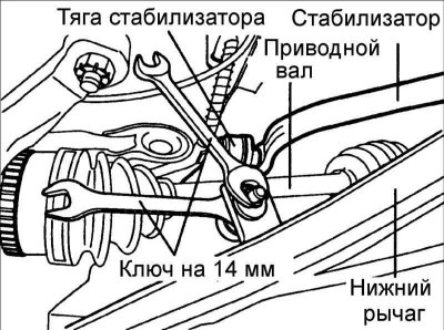
7. Secure the stabilizer link with a 14 mm open-end wrench and tighten the self-locking nut.
8. Install the washer, screw on the drive shaft mounting castle nut and secure it with a cotter pin.
9. Install the wheel.