
Removal
1. Remove the rear wheel.
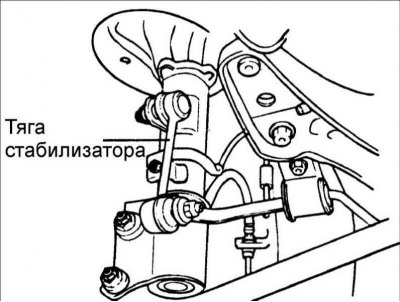
2. Disconnect the anti-roll bar link.
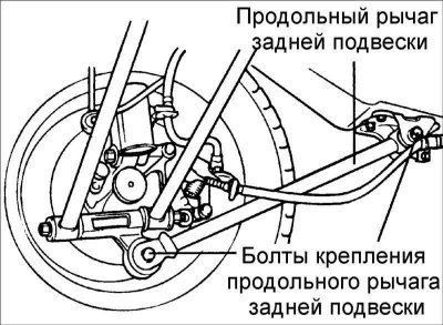
3. Remove the bolts and the rear suspension trailing arm.
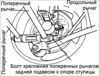
4. Remove the bolt securing the rear suspension wishbones to the hub support.
5. Support the rear beam with a jack and unscrew the bolts securing the beam to the body.
6. Remove the rear beam and arms.
Disassembly
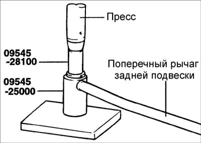
1. Install special tools 09545-28100 and 09545-25000 to the rear suspension control arm.
2. Press the bushing out of the rear suspension wishbone.
Examination
1. Check the bushing for wear and deterioration.
2. Check the levers for bending or damage.
3. Check the condition of all bolts.
Assembly
1. Lubricate the bushing and the bushing mounting location on the lever with soapy water.
2. Using special tool 09552–25000, press the bushing into the lever.
Installation
Installation is carried out in the reverse order of removal.
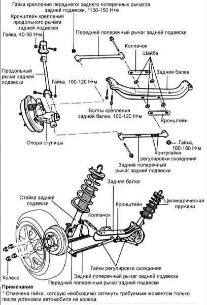
Tighten all threaded connections to the specified torques. Tightening torque:
- * Rear suspension trailing arm mounting bolts: 100–120 N·m
- Rear trailing arm bracket mounting bolts: 40–50 N·m
- Anti-roll bar bracket mounting bolts: 17–26 N·m
- Anti-roll bar links: 35–45 Nm
- * Rear suspension front/rear wishbone mounting nut: 130–150 N·m
- Rear beam mounting bolts: 100–120 N·m
Attention! * Threaded connections are marked that must be tightened to the required torque only after the vehicle has been installed on the wheels.