
Remove the lower protective cover, air filter, battery and its bracket.
After unscrewing the nut, disconnect the cable connecting the selector lever to the control valve block.
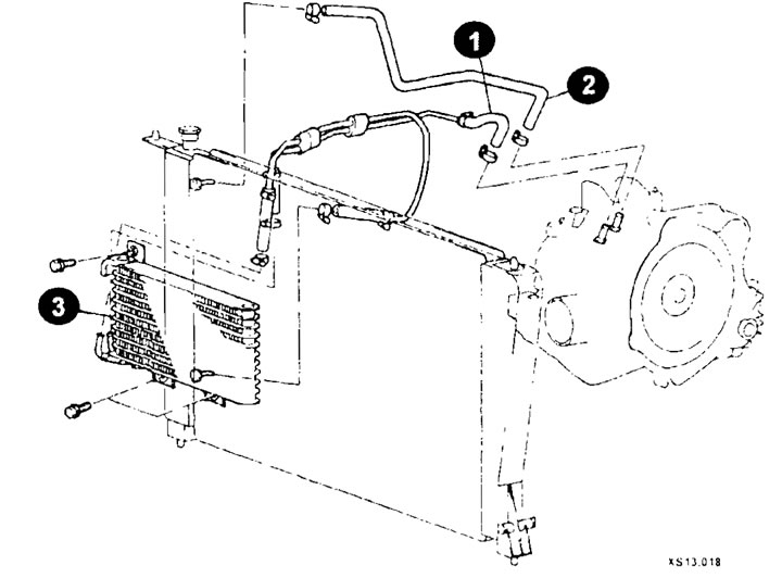
After loosening the clamps, disconnect the hoses (1) and (2) (radiator (3)) of the liquid cooling system.
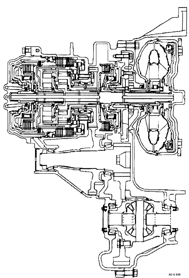
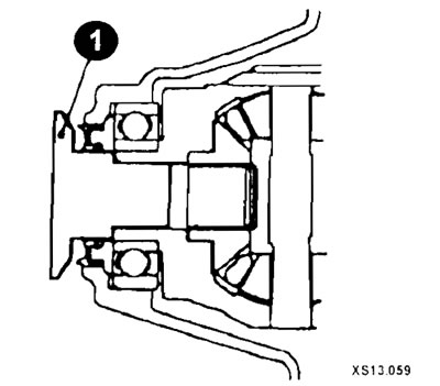
Cross section of automatic transmission
Disconnect the electrical connectors of the speed sensor (4), speed sensor (3), selector switch and solenoid valve block (see fig XS13.055).
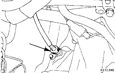
Loosen the nut and disconnect the speedometer drive cable (arrow).
Remove the starter along with the wires attached to it and secure it inside the engine compartment.
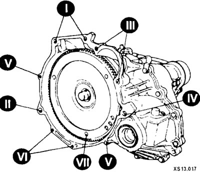
Loosen the gearbox mounting bolts in the sequence shown in the figure.
Raise the gearbox with a jack, then loosen the nut, remove the bolt, remove the gearbox stoppers and disconnect the gearbox support bracket.
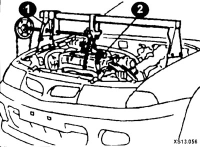
Install an engine lift with a hand hoist and a crossbar (1, 2) on the vehicle.
Disconnect the anti-roll bar links.
After removing the brake hose mounting bracket, disconnect the wheel speed sensor connector.
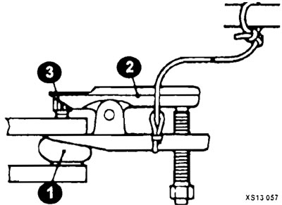
After loosening the nut (3) securing the ball joint pin (1), disconnect the steering rod end from the steering knuckle using a puller (2).
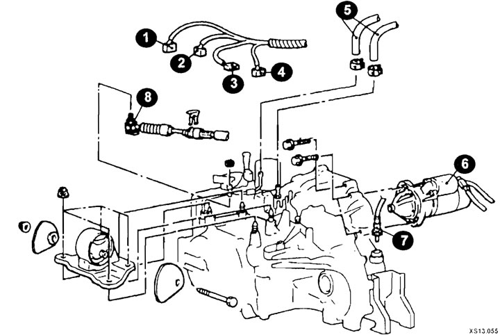
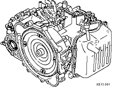
Automatic transmission mounting elements
1 - electromagnetic valve block connector;
2 - selector switch connector;
3 - speed sensor connector "B";
4 - speed sensor connector "A";
5 - cooling system hoses;
6 - starter;
7 - speedometer drive cable;
8 - connection of the selector lever cable to the control valve block.
Disconnect the lower control arm from the steering knuckle using a puller.
Remove the center beam assembly.
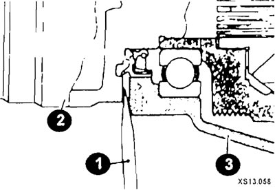
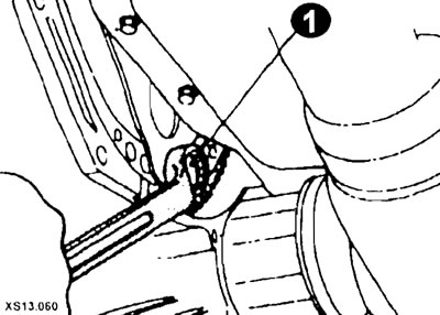
Without removing the hub and steering knuckle from the drive shaft (2), insert the crowbar (1) between the shaft (2) and the gearbox housing (3) and disconnect the shaft from the gearbox.
Hang the removed wheel drive shafts on the car body using wire.
Close the hole with a special cover (1).
Loosen the bolts and remove the gearbox support.
Loosen the bolts and remove the flywheel housing shield.
Lift the box.
While turning the engine crankshaft, loosen the bolts (1) securing the torque converter drive plate.
After unscrewing the lower bolts securing the box, lower it to the floor.
Installation
Installation is carried out in reverse order, taking into account the following:
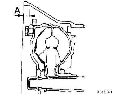
When installing the torque converter into the gearbox housing, maintain dimension A and install the gearbox assembly onto the engine (A= 12.2 mm).
Temporarily install the wheel drive shaft, ensuring that when installing the CV joint housing, the drive shaft is aligned with the mounting hole in the gearbox housing.
Install the box support limiter.