
HyundaiBook.ru
Repair Chevrolet Repair Honda Repair Toyota Repair Land Rover Repair VAZ Repair Renault Repair Nissan
English Русский
Български
Беларускі
Український
Српски
Hrvatski
Română
Polski
Slovenský
Magyar
ArticlesSitemapContacts  


  Accent   Elantra   Getz   Grandeur   Sonata   Santa Fe   Tucson   Others
Accent 1 (1994-1999) Accent 2 (1999-2005) Accent 3 (2005-2010)
  • Main
  • Accent
  • LC (1999-2005)
  • Power unit
  • SOHC engines
  • Connecting rods — removal and installation

Connecting rods — removal and installation (Hyundai Accent LC)

0
Contents: Piston and connecting rod ⇓ Removal ⇓ Examination ⇓ Installation ⇓
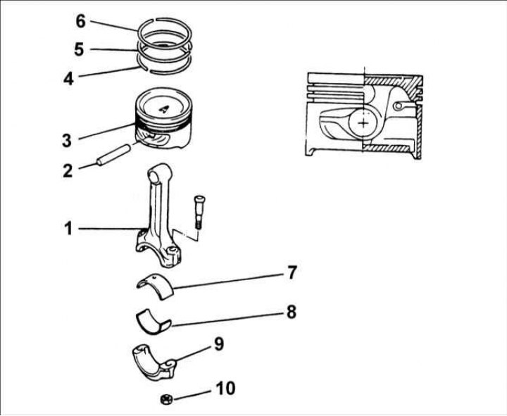
Piston and connecting rod


1 – connecting rod; 2 – piston pin; 3 – piston; 4 – oil scraper ring; 5 –…

1 – connecting rod; 2 – piston pin; 3 – piston; 4 – oil scraper ring; 5 – compression ring No.2; 6 – compression ring No.1; 7 – upper connecting rod bearing shell; 8 – lower connecting rod bearing shell; 9 – connecting rod cover; 10 – nut, 32–35 Nm.


Removal


Removal


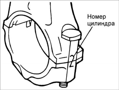
Warning: Keep the connecting rod caps with the corresponding connecting rods for proper reinstallation into the engine cylinders.


1. Loosen the nuts and remove the connecting rod cap and the lower connecting rod bearing shell. To protect the crankshaft journals, place sections of rubber or plastic tube on the connecting rod cap mounting bolts.


2. Use a wooden block or a hammer handle to push the piston and connecting rod out of the cylinder.

Examination


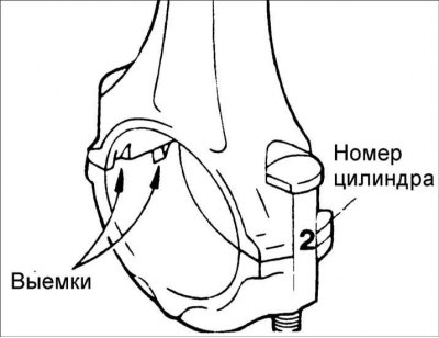
1. When installing, make sure that the connecting rod and connecting rod cap match the cylinder number they are being installed in. When installing a new connecting rod, make sure that the marks that determine its position are on the same side as the marks on the other connecting rods.

2. Replace the connecting rod if there is damage on both bearing surfaces. Also replace the connecting rod if there is wear or damage on the surface mating with the piston pin.
2. Replace the connecting rod if there is damage on both bearing surfaces. Also…


3. Check the bend of each connecting rod. If necessary, replace the connecting rods. Replace the connecting rod together with the connecting rod cap.
  • Allowable bending of connecting rod: 0.05 mm/ 100 mm length
  • Permissible twisting of the connecting rod: 0.1 mm / 100 mm length

Installation


Installation


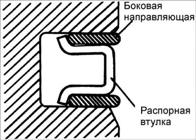
1. Install the spacer sleeve.


2. Install the upper side guide. To install the side guide, first place one end of the side guide between the piston ring groove wall and the spacer sleeve, press it down, then press it around the perimeter to install it into the piston groove.

Warning: Do not use pliers to spread the piston rings when installing the side guide.
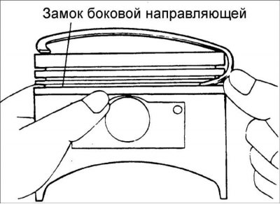

Warning: Do not use pliers to spread the piston rings when installing the side…


3. Install the low side guide in the same manner.

4. Using piston ring pliers, install compression ring No.2.
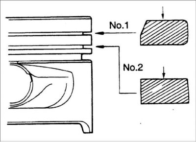
4. Using piston ring pliers, install compression ring No.2.


5. Using piston ring pliers, install compression ring No.1.

6. Apply a thin layer of motor oil to the piston and piston rings.
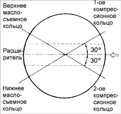
6. Apply a thin layer of motor oil to the piston and piston rings.


7. Position the piston ring locks as shown in the figure.


8. Using a special tool, compress the piston rings onto the piston.

The article is copied from this website (hyundaibook.ru)

9. Place the piston with piston rings over the first cylinder, with the mark on the piston facing the front of the cylinder block.

10. Using a hammer handle, press the piston into the cylinder until the lower head of the connecting rod is seated on the crankshaft journal.

11. Install the connecting rod bearing into the connecting rod cap.
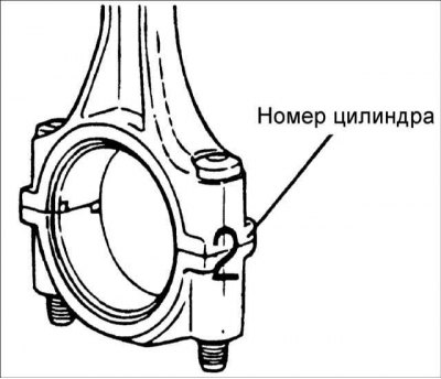
11. Install the connecting rod bearing into the connecting rod cap.


12. Install the connecting rod cover and secure with nuts.

Tightening torque: 32–35 Nm
Tightening torque: 32–35 Nm


13. Using a feeler gauge inserted between the connecting rod and the crankshaft, measure the connecting rod side clearance.
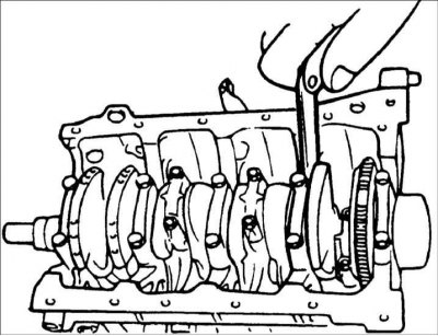
  • Nominal connecting rod side clearance: 0.10–0.25 mm
  • Maximum clearance: 0.40 mm
This article is available at russian, bulgarian, belarusian, ukrainian, serbian, croatian, romanian, polish, slovak, hungarian
This article has been reviewed by: Konstantin Smirnov
Add to social network:

Previous
Accent 2: SOHC engines
Next

Camshaft — Removal and Installation
Valves — removal and installation
Replacing the valve guide bushing
Replacing the valve seat
Hydraulic valve clearance compensators
Crankshaft — removal and installation
Flywheel — removal and installation
Piston pin — removal and installation
Exhaust manifold
Intake manifold and air chamber
We recommend other articles on the topic of Hyundai manuals:

Pistons and connecting rods — removal Hyundai Elantra 1 (1990-1995, petrol)
Pistons and connecting rods — removal and installation Hyundai Getz (2002-2011)
Pistons and connecting rods — removal and installation Hyundai Sonata 3 (1993-1998)
Socket for connecting additional equipment Hyundai Santa Fe 2 (2007-2012, petrol)
Disassembly and assembly of the connecting rod and piston group Hyundai Matrix (2001-2010, petrol)

Link in different formats to this article

Visitor comments
No comments yet


How much will 25 + 48 ?


Accent 3 (2005-2010) 
  • General information
  • User manual
  • Maintenance
  • Power unit
  • Engine repair
  • Cooling and lubrication system
  • Power and exhaust system
  • Engine electrical equipment
  • Engine management
  • Transmission
  • Clutch
  • Mechanical gearbox
  • Automatic gearbox
  • Chassis
  • Front suspension
  • Rear suspension
  • Wheels and tires
  • Steering
  • Brake system
  • Body
  • Exterior (external elements)
  • Interior (internal elements)
  • Heating and ventilation
  • Electrical equipment
  • Equipment and devices
  • Electrical circuits
Accent 2 (1999-2005) 
  • User manual
  • Control devices
  • Starting engine and driving
  • Troubleshooting
  • Power unit
  • SOHC engines
  • DOHC engines
  • Lubrication system
  • Cooling system
  • Decreased toxicity
  • Fuel system
  • Ignition system
  • Transmission
  • Clutch
  • Mechanical gearbox
  • Automatic gearbox
  • Axles and drive shafts
  • Chassis
  • Car suspension
  • Steering
  • Brake system
  • Body
  • Exterior (external elements)
  • Interior (internal elements)
  • Air conditioning system
  • Electrical equipment
  • Equipment and devices
  • Power devices
Accent 1 (1994-1999) 
  • General information
  • Maintenance
  • Power unit
  • SOHC engines
  • DOHC engines
  • Cooling system
  • Intake and exhaust systems
  • Fuel supply (1.3 l, injection)
  • Fuel supply (1.5 l, injection)
  • Fuel supply (carburetor)
  • Transmission
  • Clutch
  • Manual gearbox
  • Automatic gearbox
  • Drive shafts
  • Chassis
  • Car suspension
  • Steering
  • Brake system
  • Body
  • Body elements
  • Electrical equipment
  • Equipment and devices
  • Electrical circuits
HyundaiBook.ru © 2018-2026 · Mobile version · Sitemap: EN BG BY UA RS HR RO PL SK HU · Administration · Site search · Hyundai owners Accent 1 · Accent 2 · Accent 3 · Elantra 1 · Elantra 2 · Elantra 3 · Getz · Sonata 3 · Sonata 4 · Santa Fe 2 · Tucson 1 · Tucson 2 · Matrix ·
This site uses cookies to optimize its functionality. By continuing, you agree to our terms.