


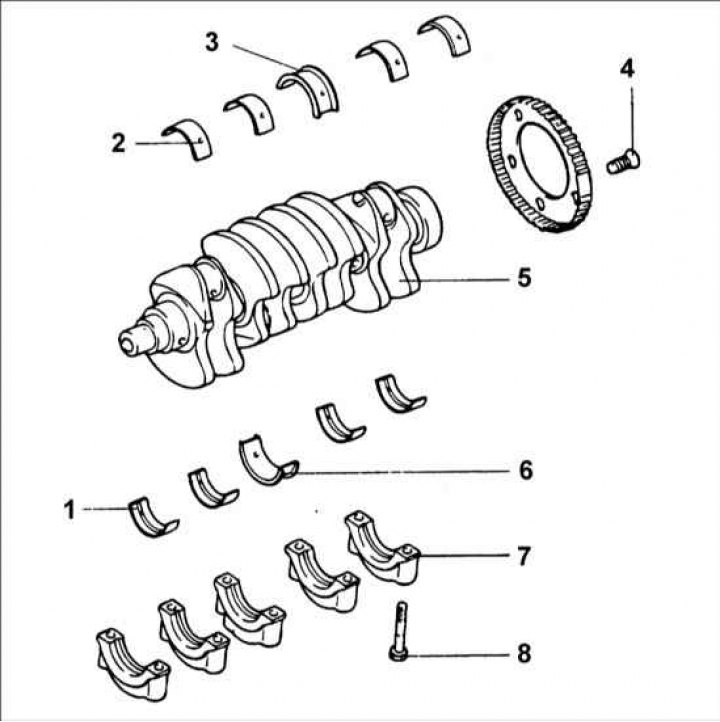
1 – lower shell of the crankshaft main bearing; 2 – upper shell of the crankshaft main bearing; 3 – upper bearing of the crankshaft; 4 – crankshaft angle sensor; 5 – crankshaft; 6 – lower bearing of the crankshaft; 7 – crankshaft main bearing cap; 8 – bolt, 55–60 Nm.
Removal
1. Remove the timing belt, front cover, flywheel and oil pan.
2. Remove the rear cover from the cylinder block and the rear crankshaft seal ring.
3. Loosen the nuts and remove the connecting rod caps.
4. Remove the bolts and crankshaft main bearing caps.
5. Remove the crankshaft angle sensor rotor.
Warning! Mark the crankshaft main bearing caps to ensure that they are installed in the correct locations and positions.
Examination
1. Check the crankshaft main and connecting rod bearing journals for wear and tear. Check the crankshaft oil holes for blockage.
2. Using a micrometer, measure the crankshaft journal diameters in two diametrically opposite directions. If there is wear or ovality, regrind the crankshaft. Regrind the crankshaft journals only to the next repair size. If the crankshaft is regrind to the repair size +0.50 mm, heat treat the shaft to increase its durability.
- Crankshaft main journal diameter: 50 mm
- Connecting rod diameter 45 mm
- Ovality and taper of crankshaft journals: no more than 0.01 mm
3. Check the connecting rod and main bearings for local corrosion, wear, and other damage. Replace the bearings if necessary.
Measuring the clearance of main and connecting rod bearings
To measure the clearance of the main and connecting rod bearings, measure the crankshaft journal diameters and the corresponding bearing inside diameters. The clearance value is the difference between the bearing inside diameter and the corresponding crankshaft journal diameter.
- Clearance of main bearings No.1, 2, 4, 5 of the crankshaft: 0.028–0.045 mm
- Clearance of main bearing No.3 of crankshaft: 0.034–0.520 mm
- Crankshaft connecting rod bearing clearance: 0.024–0.042 mm
Measuring main and connecting rod bearing clearance using a Plastigage plastic calibrated rod
1. Clean the main and connecting rod journals of the crankshaft from grease, and blow out the lubrication holes with compressed air.
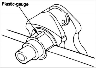
2. Install the main bearing shells onto the engine block. Install the crankshaft onto the main bearing shells in the engine block. Install the remaining main bearing shells into the crankshaft main bearing caps. Place lengths of Plastigage on the crankshaft main bearing journals.
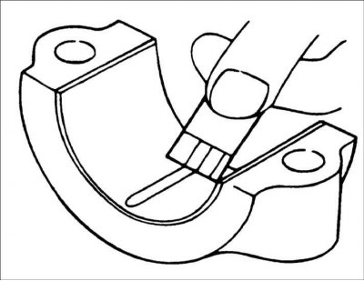
3. Install the main bearing caps according to the marking. Tighten the crankshaft main bearing cap bolts in the specified sequence. Do not rotate the engine crankshaft when measuring the crankshaft main bearing clearance. Unscrew the bolts and remove the crankshaft main bearing caps. Measure the width of the deformed Plastigage plastic rod with a measuring template and determine the clearance value.
4.If the clearance exceeds the maximum permissible value, regrind the crankshaft journals and use oversized repair bearings.
Oil sealing rings
Check the front and rear oil seal rings for damage or wear on the sealing lips. If any defects are found, replace the seal ring.
Crankshaft angle sensor rotor
1. Remove the crankshaft angle sensor rotor.
2. Inspect the crankshaft angle sensor rotor for damage, cracks, and wear and replace if necessary.
3. Check the clearance between the crankshaft angle sensor rotor and the crankshaft angle sensor.
- Clearance between crankshaft angle sensor rotor and crankshaft angle sensor: 0.5–1.0 mm
Execution order
Warning! Measure the sensor installation depth, i.e. the distance from the top of the crankshaft angle sensor rotor teeth to the outside of the cover.
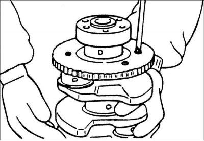
Calculate the difference between the length of the crankshaft angle sensor and its installation depth.
Installation
1. Install the upper main bearing shells onto the engine block. When reinstalling the shells, install them in the same locations they were in before removal.
2. Before installing the crankshaft, apply a thin film of clean engine oil to all sliding surfaces. Install the crankshaft on the main bearing shells in the cylinder block.
3. Install the remaining main bearing shells into the crankshaft main bearing caps. Install the crankshaft main bearing caps according to the markings, with the arrow on each cap facing the crankshaft pulley. Tighten the crankshaft main bearing cap bolts in a specific sequence in 2 or 3 stages in the following order: center, #2, #4, front, and rear.
Tightening torque:
- Main bearing caps: 55–60 N·m
- Connecting rod bearing caps: 32–35 N·m
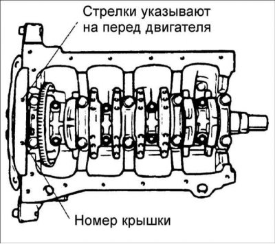
4. Turn the crankshaft and check that it rotates easily and smoothly. Place the dial indicator tip on the front end of the crankshaft. Move the crankshaft along the axis until it stops and set the dial indicator scale to zero. Move the crankshaft along the axis in the other direction until it stops and read the axial play values on the dial indicator scale.
Crankshaft axial clearance: 0.050–0.175 mm
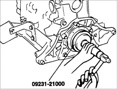
5. Lubricate the outer surface of the new rear sealing ring with engine oil. Using special tool 09231-22000, install the sealing ring until it stops in the rear cover socket.
6. Install the sealing ring cover, gasket and tighten the 5 bolts. When installing, lubricate the working edges and the outer surface of the sealing ring with clean engine oil.
7. Install the back cover and secure it with bolts.
8. Install the connecting rod caps.
9. Install the flywheel, front cover, oil pan and timing belt.