
Withdrawal
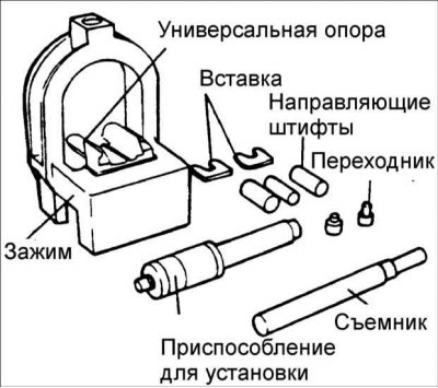
1. Disassembly and reassembly of the piston and connecting rod requires the use of special tools 09234-33001.
2. Install the universal supports in the clamp between the connecting rod and the piston.
3. Insert the puller through the hole in the arch of the clamp.
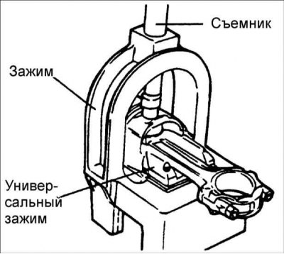
Warning! Insert the clamp with the piston, connecting rod and puller under the press slider.
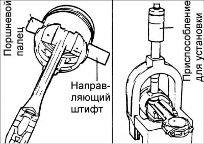
4. Pull the piston pin out of the piston with a puller.
Installation
1. Install the guide pins through the piston into the connecting rod, and install the piston pin on the other side of the piston.
Warning! The guide pins determine the position of the connecting rod in the piston. Once the piston, connecting rod, piston pin and piston pin insertion tool have been installed, the guide pins also determine their position in the clamp.
2. Install the piston assembly on the clamp with the guide pin supporting the connecting rod in the piston pin.
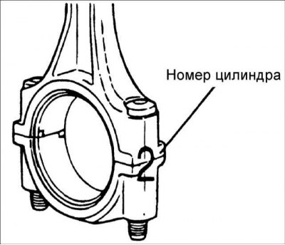
3. Check the correct positioning of the piston and connecting rod and, by turning the knurled nut, secure the numbered bushing to the shaft.
4. Insert the shaft through the hole in the arch of the clamp. Press the piston pin into the connecting rod until the sleeve on the shaft contacts the top of the arch of the clamp, and the pilot pin should fall out of the piston.
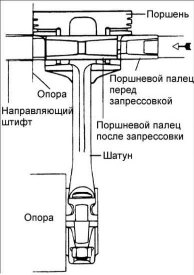
Warning! The piston pin pressing force must not exceed 22500 N.
Pressing depth: 0.3-0.5 mm
Examination
Piston and piston pin
1. Check the outer surface of the piston for damage, wear, or uneven wear. If necessary, replace the piston.
2. Check each piston ring for damage and uneven wear. If necessary, replace piston rings.
Warning! When replacing a piston, the piston rings must also be replaced.
3. Check the piston pin by inserting it into the piston bore. The piston pin should smoothly enter the piston when pressed by hand (at room temperature).
Piston rings
1. Insert a new piston ring into the piston groove and use a feeler gauge to measure the gap between the piston ring and the groove wall. If the clearance exceeds the maximum allowable value, replace the piston.
Gap between piston ring and piston groove:
- First compression ring: 0.04-0.085mm
- Second compression ring: 0.04-0.085mm
- Maximum allowable gap: 0.1 mm
2. Measure the piston ring gap by manually inserting the piston ring into the engine cylinder. Use the piston crown to push the piston ring into the bottom of the cylinder. Use a feeler gauge to measure the clearance in the piston ring lock.
Piston ring clearance:
- First compression ring: 0.15-0.30mm
- Second compression ring: 0.20-0.40mm
- Oil scraper ring: 0.20-0.70 mm
- Maximum allowable gap: 1.0 mm
Installation
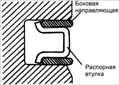
1. Install spacer sleeve.
2. Install the top side guide. To install the side guide, first place one end of the side guide between the wall of the piston ring groove and the spacer, press it in, then press it all the way into the piston groove.
Warning! Do not use piston ring pliers when installing the side guide.
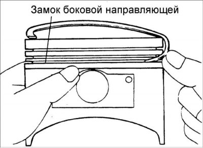
3. Install the low side rail in the same way.
4. Using pliers to open the piston rings, install compression ring No. 2.
5. Using pliers to open the piston rings, install the compression ring No. 1.
6. Apply a thin coat of engine oil to the piston and piston rings.
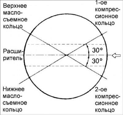
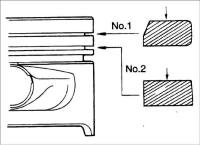
7. Position the piston ring locks as shown.
8. Compress the piston rings on the piston with a special tool.
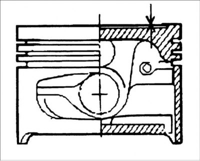
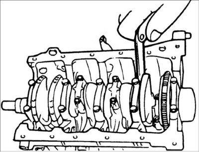
9. Install the piston with piston rings over the first cylinder, with the mark on the piston facing the front of the cylinder block.
10. Using a hammer handle, press the piston into the cylinder so that the lower end of the connecting rod rests on the crankshaft journal.
11. Install the connecting rod bearing into the connecting rod cap.
12. Install the connecting rod cap and secure with nuts.
Tightening torque: 32-35 Nm
13. Using a feeler gauge inserted between the connecting rod and the crankshaft, measure the connecting rod backlash.
- Rated connecting rod side clearance: 0.10-0.25mm
- Maximum allowable gap: 0.40 mm