
2. Remove the rear wheel from the hub.
Caution: When removing the rear wheel with the tire, be careful not to damage the hub studs.
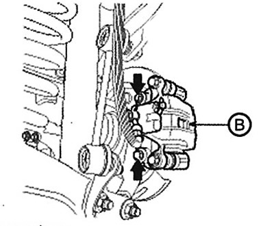
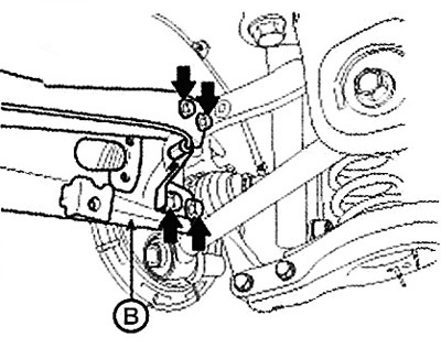
3. Loosen the caliper mounting bolts and hang the caliper (B) using wire on the suspension elements.
Note: Tightening torque: 78.4 - 98.0 Nm.
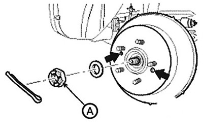
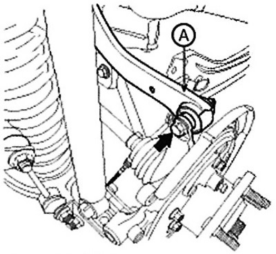
4. Remove the castle nut (A) from the front hub while keeping the brake pedal depressed.
Note: Tightening torque: 196.1 - 274.5 Nm.
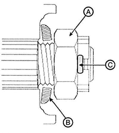
Caution: Before tightening the castle nut (A) and installing the cotter pin (C), it is necessary to put the washer (B) in place with the convex surface outward. Do not reuse the cotter pin (C) during assembly.
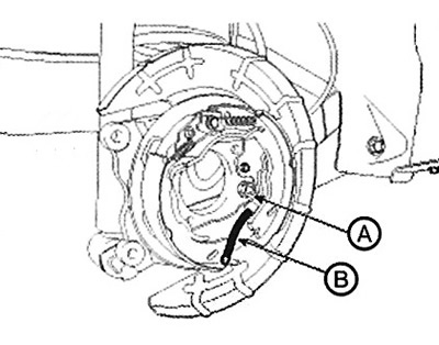
5. Remove the brake pads (A).
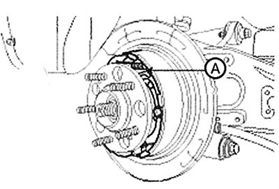
6. Disconnect the parking brake cable (B) from the brake shoe (A).
7. Remove the stopper (B) of the parking brake cable (A).
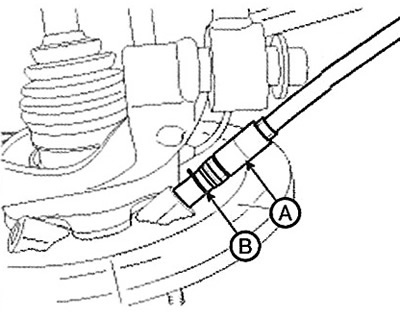
8. Remove the wheel speed sensor (A) from the wheel support.
Note: Tightening torque: 6.8 - 10.8 Nm.
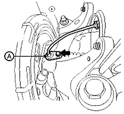
9. Remove the auxiliary lever (A) from the wheel support.
Note: Tightening torque: 137.2 - 156.9 Nm.
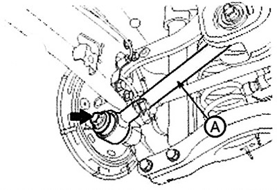
10. Remove the trailing arm (B) from the wheel support.
Note: Tightening torque: 34.3 - 53.9 Nm.
11. Remove the upper arm (A) from the wheel support.
Note: Tightening torque: 98.0- 117.6 Nm.
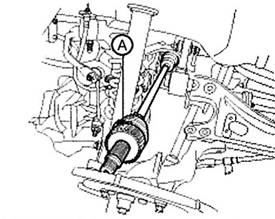
12. Remove the wheel support and disconnect the drive shaft (A) from the hub.
[The article is borrowed from the website: www.HyundaiBook.ru]
13. Remove the drive shaft (B) from the final drive housing by installing a pry bar (A) between the housing and the joint housing.
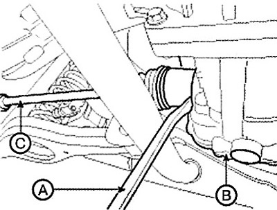
Attention.
Use the pry bar (A) carefully to avoid damaging the final drive and joint.
Do not insert the pry bar (A) too deeply to avoid damaging the seal.
Do not remove the drive shaft using excessive force as this may cause the joint components to become displaced and result in damage to the boot or bearing.
Cover the main gear housing opening with a cap to prevent contamination.
Provide adequate support for the drive shaft.
Replace the snap ring if the drive shaft is removed from the final drive housing.
14. Installation is carried out in the reverse order of removal.