
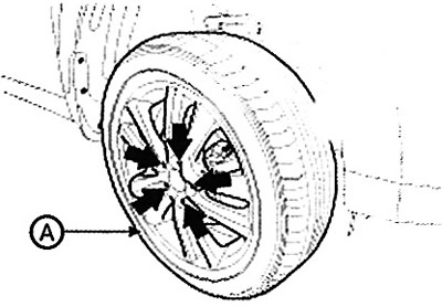
2. Remove the front wheel (A) from the hub.
Note: Tightening torque: 88.2 - 107.8 Nm.
Caution: Be careful not to damage the hub studs when removing the front wheel (A).
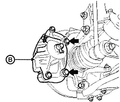
3. Loosen the brake caliper mounting bolts and hang the caliper (B) assembly on the wire on the suspension elements.
Note: Tightening torque: 78.4 - 98.0 Nm.
4. Remove the castle nut (A) from the front hub while keeping the brake pedal depressed.
Note: Tightening torque: 196.1 - 274.5 Nm.
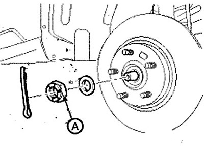
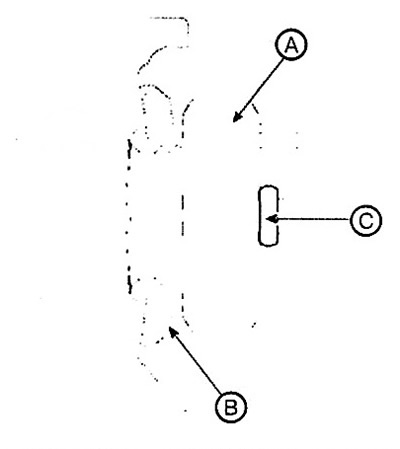
Caution: Before tightening the castle nut (A) and installing the cotter pin (C), it is necessary to put the washer (B) in place with the convex surface outward. Do not reuse the cotter pin (C) during assembly.
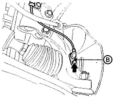
5. Remove the wheel speed sensor (B).
Note: Tightening torque: 6.8 - 10.8 Nm.
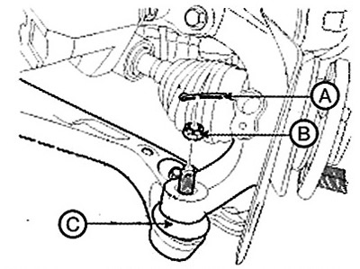
6. Disconnect the steering rod ball joint (C) from the steering knuckle.
(1) Remove the cotter pin (A).
(2) Loosen the castle nut (B).
Note: Tightening torque: 34.3 - 44.1 Nm.
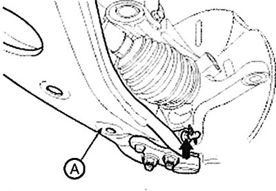
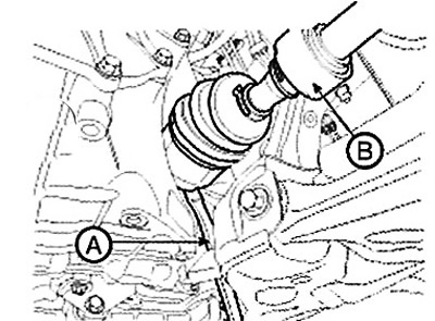
7. Loosen the lower arm mounting bolt (A) on the knuckle.
Note: Tightening torque: 98.0 - 117.6 Nm.
8. Disconnect the end (A) of the drive shaft from the steering knuckle.
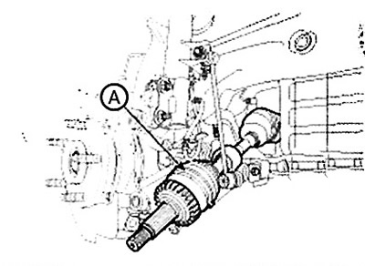
9. Remove the drive shaft assembly (A) from the inner shaft.
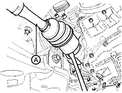
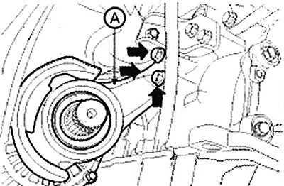
10. Loosen the inner shaft mounting bolts and then disconnect the inner shaft (A).
11. Insert a pry bar (A) between the gearbox housing and the joint housing. Disconnect the drive shaft (B) from the gearbox housing.
12. Installation is performed in the reverse order of removal.
Attention.
- Use the pry bar (A) carefully to avoid damaging the gearbox and joint.
- Do not insert the pry bar (A) too deeply to avoid damaging the seal.
- Do not pull the drive shaft with excessive force as this may cause the joint components to become displaced and result in damage to the boot or bearing.
- Plug the hole in the gearbox housing with a cap to prevent dirt from getting inside.
- Provide adequate support for the drive shaft.
- Replace the snap ring with a new one each time the drive shaft is removed from the transmission housing.