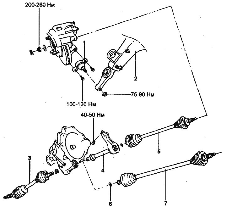
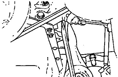
Front drive shafts.
1 - lower ball joint, 2 - lower arm of the front suspension, 3 - left drive shaft, 4 - intermediate drive shaft assembly with bearing, 5 - right drive shaft (2.7 l engines), 6 - retaining ring (2.7 l engines), 7 - right drive shaft (engines other than 2.7 l).
Removal
1. Jack up the car, unscrew the bolts and remove the front wheels.
- Tightening torque: 90-110 Nm
2. Drain the transmission oil/working fluid from the gearbox (see chapter "Maintenance and general check and adjustment procedures").
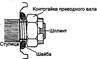
3. Loosen the drive shaft locknuts.
- a) Remove the cotter pins and lock nut caps.
- b) Loosen the lock nuts.
- Tightening torque: 200-260 Nm
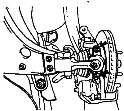
4. Loosen the bolts and disconnect the lower ball joints from the steering knuckles.
- Tightening torque: 100-120 Nm
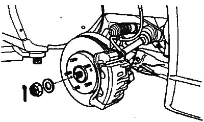
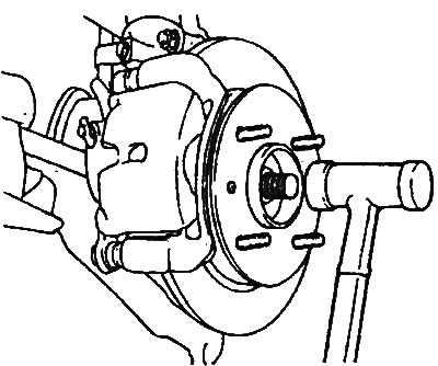
5. Using light blows from a plastic-faced hammer, disconnect the drive shaft from the wheel hub.
6. Using a pry bar, disconnect the drive shaft from the gearbox.
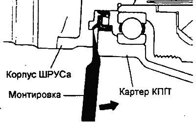
Attention:
- Be careful when using the pry bar so as not to damage the drive shaft joint.
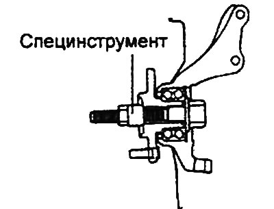
- When loosening the drive shaft lock nut, the hub bearing should not be loaded with the weight of the vehicle. If it is necessary to load the bearing (in case of moving the vehicle), install the special tool and secure it with a nut as shown in the figure.
7. (Models with 2.7L engine) Remove the tension roller and the accessory drive belt (see chapter "Engine - mechanical part").
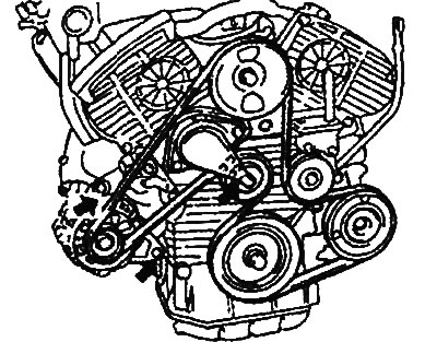
8. (Models with 2.7L engine) Remove the generator (see chapter "Starting system").
9. Loosen the bolts and, using a pry bar, disconnect the bearing bracket from the cylinder block.
10. Remove the intermediate drive shaft from the gearbox housing.
Examination
1. Make sure there is no noticeable play in the outer hinge.
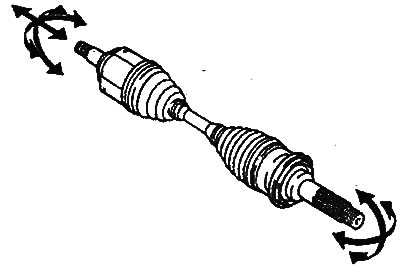
2. Make sure that the inner joint slides smoothly in the axial direction.
3. Make sure that there is no noticeable play in the inner joint in the radial direction.
4. Make sure the covers are not damaged.
Installation
1. Installation of drive shafts is carried out in the reverse order of removal; tightening torques for bolts and nuts are indicated in the text describing the removal procedure and in the assembly drawing "Front drive shafts".
2. When installing, please pay attention to the following operations:
- Apply transmission oil to the splines of the shafts and mating parts.
- Position the retaining ring so that the ring lock faces downward.
- After installing the drive shaft, check that the shaft is securely fixed and cannot be removed by hand. Place a washer under the drive shaft lock nut so that it is positioned with the convex side outward, as shown in the figure.