
Contents: Intake manifold ⇓ Removal and installation ⇓
Intake manifold
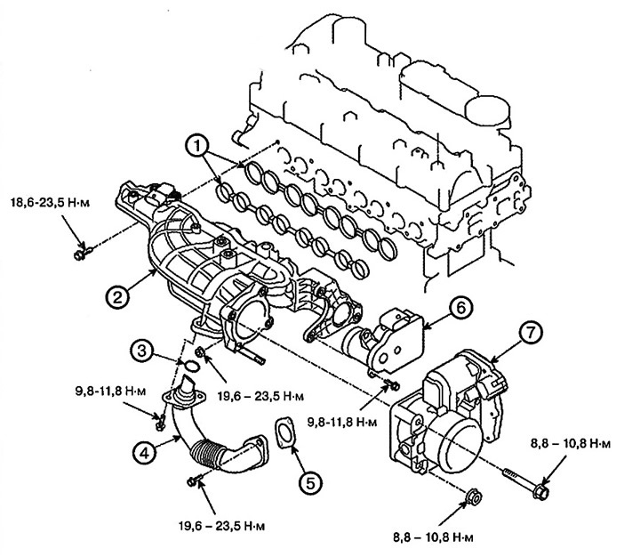
1. Intake manifold gasket
2. Intake manifold
3. O-ring of the exhaust gas recirculation (EGR)nozzle assembly
4. Exhaust Gas Recirculation (EGR) Pipe Assembly
5. Installation of the exhaust gas recirculation (EGR)nozzle assembly
6. Valve for controlling the creation of vortex flows in the fuel-air mixture
7. Air intake control valve
Removal and installation
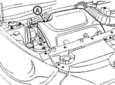
1. Remove the engine cover (A).
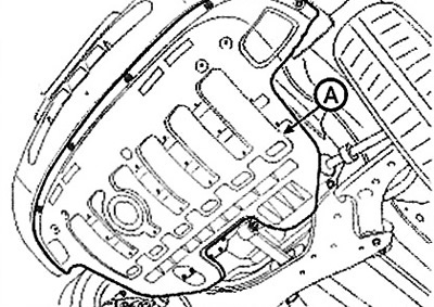
2. Remove the oil pan guard (A).
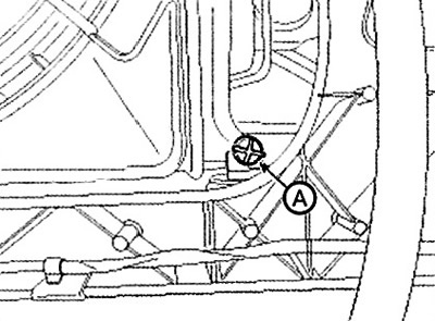
3. Loosen the radiator drain plug (A) and drain the engine coolant. Remove the radiator cap to speed up drainage.
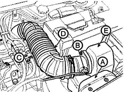
4. Remove the air filter assembly.
(1) Remove the air duct (A).
(2) Disconnect the mass air flow sensor (AFS) connector (B).
(3) Disconnect the breather hose (C).
(4) Disconnect the air intake hose (D) and remove the air cleaner (E) assembly.
Note: Tightening torque:
- Clamps: 2.9-4.9 Nm.
- Bolts: 7.8-9.8 Nm.
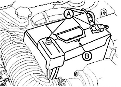
5. Disconnect the battery terminals (A) and remove the battery (B).
Note:
Tightening torque:
(-) terminal: 4.0-6.0 Nm. (+) terminal: 7.8 - 11.8 Nm. Bracket bolt: 9.8 - 11.8 Nm.
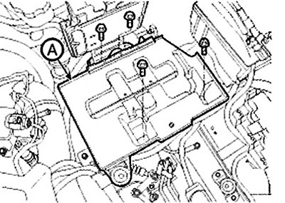
6. Remove the battery tray (A).
Note: Tightening torque: 9.8 - 11.8 Nm.
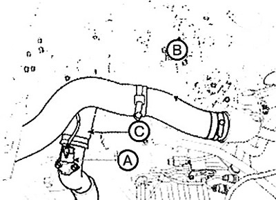
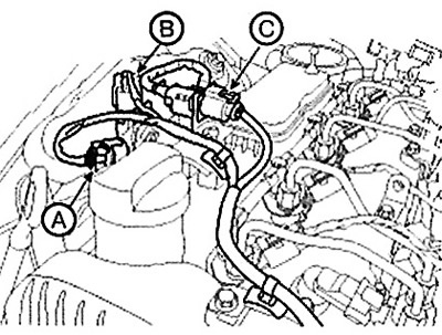
7. Disconnect the intake air temperature sensor connector (A) and disconnect the inlet (B) and outlet (C) pipes and the intercooler hose.
Note:
Tightening torque: Clamps: 4.9 - 6.9 Nm. Bolt: 9.8 - 11.8 Nm.
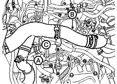
Standard power
Disconnect the boost pressure sensor (BPS) connector (A) and disconnect the inlet (B) and outlet (C) pipes and the intercooler hose.
Reduced power
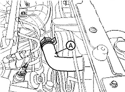
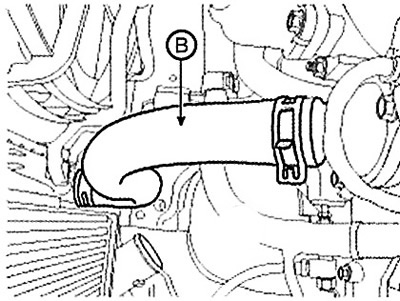
8. Remove the upper (A) and lower (B) radiator hoses.
 |
 |
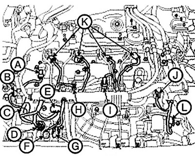
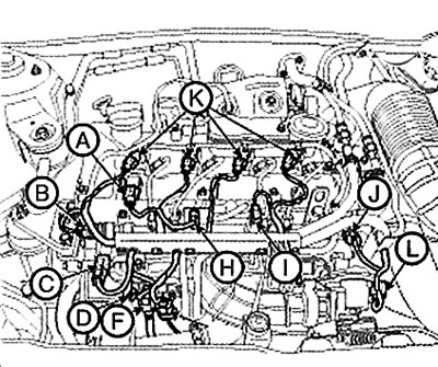
9. Disconnect the engine wire harness connectors and remove the wire harness clamps from the cylinder head cover and intake manifold.
(1) Disconnect the pressure change sensor connector (A). (With diesel particulate filter).
(2) Disconnect the exhaust gas temperature sensor connector (B). (With diesel particulate filter).
(3) Disconnect the oxygen sensor connector (C).
(4) Disconnect the camshaft position sensor (CMPS) connector (A).
(5) Disconnect the fuel rail pressure sensor connector (B).
(6) Disconnect the glow plug connector (C).
(7) Disconnect the fuel pressure regulator connector (D).
(8) Disconnect the boost pressure sensor (BPS) connector (E). (For standard power engines only.).
(9) Disconnect the oil pressure sensor connector (F).
(10) Disconnect the crankshaft position sensor (CKPS) connector (G).
(11) Disconnect the connector (H) of the exhaust gas cooling (EGR) valve.
(12) Disconnect the fuel temperature sensor connector (I).
(13) Disconnect the fuel rail pressure regulator connector (J).
(14) Disconnect the injector connectors (K).
(15) Disconnect the air supply control valve connector (L).
Standard power
Reduced power
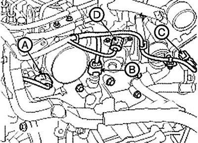
(16) Disconnect the connector (A) of the swirl control actuator.
(17) Disconnect the coolant temperature sensor (ECTS) connector (B).
(18) Disconnect the connector (C) of the electric variable geometry turbocharger (E-VGT) actuator.
(19) Disconnect the exhaust gas recirculation (EGR) actuator connector (D).
(20) Disconnect the generator connector (A) and cable (B).
(21) Disconnect the starter connector (C) and cable (D).
(22) Disconnect the air compressor switch connector (E).
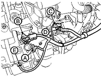
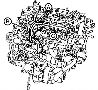
10. Remove the wire harness protector (A).
11. Disconnect the fuel hose (A), high pressure pipes (B) and vacuum hose (C) of the exhaust gas recirculation (EGR) system.
(20) Disconnect the generator connector (A) and cable (B).
(21) Disconnect the starter connector (C) and cable (D).
(22) Disconnect the air compressor switch connector (E).
10. Remove the wire harness protector (A).
Note: Reuse of the high pressure fuel line is not permitted.
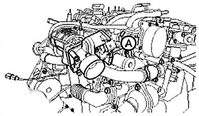
12. Remove the air control valve (A).
Note: Tightening torque: 8.8 - 10.8 Nm.
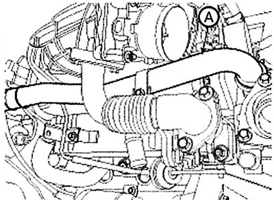
13. Remove the coolant outlet pipe (A).
Note: Tightening torque: 7.8 -11.8 Nm.
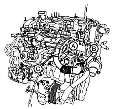
14. Remove the exhaust gas recirculation (EGR) pipe assembly (A).
Note:
Tightening torque:
- Bolts (B): 19.6 - 23.5 Nm.
- Bolts (C): 9.8 - 11.8 Nm.
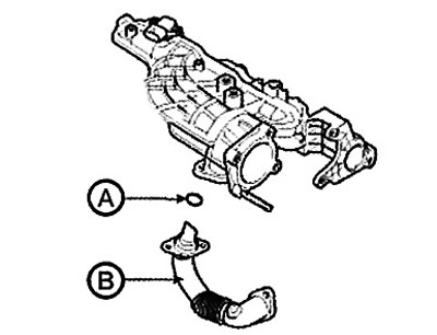
Before installing the exhaust gas recirculation (EGR) pipe (B), be sure to install the O-ring (A) into the intake manifold.
Caution: If the O-ring is inserted into the intake manifold when installing the EGR pipe, it may be damaged, resulting in exhaust gas leakage.
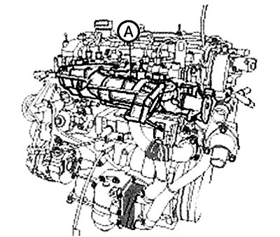
15. Remove the intake manifold (A) with the gasket (B).
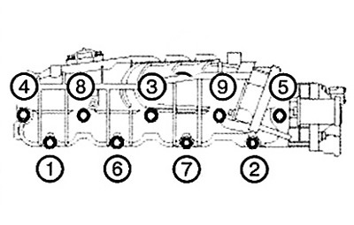
When installing the intake manifold, pre-tighten the bolts and nuts, then tighten them to the specified torque in the specified order.
Note: Tightening torque: 19.6 - 23.5 Nm.
Caution: Avoid allowing foreign matter to enter the inlet.
[This publication is based on information from the portal: HyundaiBook]
16. Install in the reverse order of removal.