
2. Disconnect the engine wiring harness connectors.
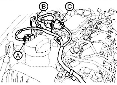
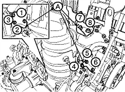
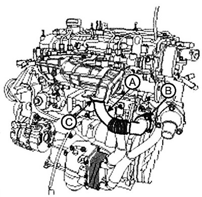
(1) Disconnect the pressure change sensor connector (A). (With diesel particulate filter).
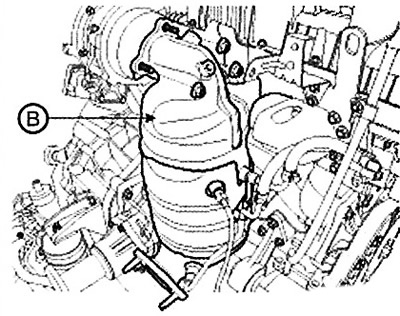
(2) Disconnect the exhaust gas temperature sensor connector (B). (With diesel particulate filter).
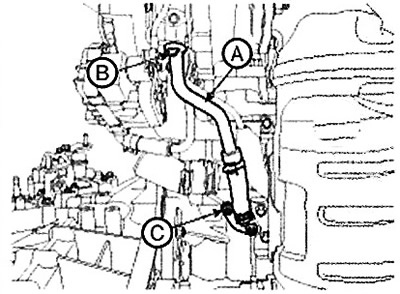
(3) Disconnect the oxygen sensor connector (C).
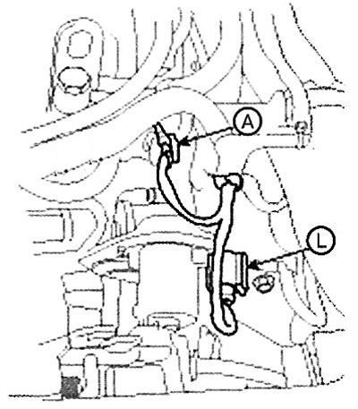
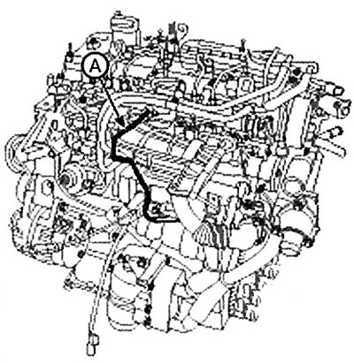
(4) Disconnect the fuel rail pressure regulator connector (A).
(5) Disconnect the air control valve connector (B).
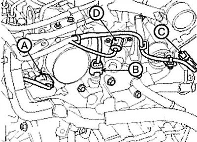
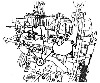
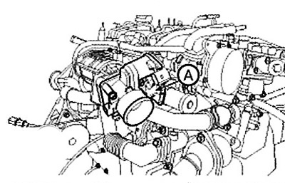
(6) Disconnect the connector (A) of the air-fuel mixture vortex control actuator.
(7) Disconnect the coolant temperature sensor (ECTS) connector (B).
(8) Disconnect the connector (C) of the electric variable geometry turbocharger (E-VGT) actuator.
(9) Disconnect the exhaust gas recirculation (EGR) actuator connector (D).
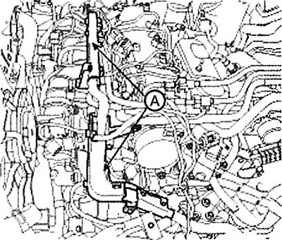
3. Remove the wire harness protector (A).
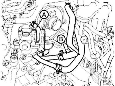
4. Disconnect the turbocharger water hose (A). (For standard power engines only.).
5. Disconnect the heater hose (B).
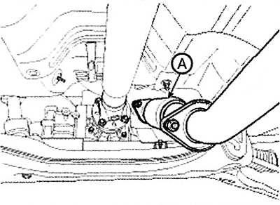
6. Remove the front muffler (A).
Note: Tightening torque: 39.2-58.8 Nm
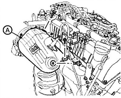
7. Remove the heat shield (A) of the diesel particulate filter (or heated catalytic converter (WCC)).
Note: Tightening torque: 17.7-21.6 Nm.
8. Remove the DPF (or heated catalytic converter (WCC)) converter assembly support bracket (A).
Note: Tightening torque: 44.1-53.9 Nm.
When installing the exhaust manifold, pre-tighten the bolts, then tighten them to the specified torque in the specified order.
9. Remove the diesel particulate filter (or heated catalytic converter (WCC)) converter assembly (A).
Note: Tightening torque: 49.0-68.6 Nm.
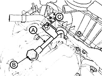
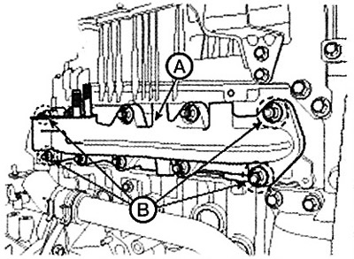
10. Remove the oil drain pipe (A) from the turbocharger.
Note:
Tightening torque:
- Bolts (B): 9.8 - 11.8 Nm.
- Nuts (C): 19.6 - 26.5 Nm.
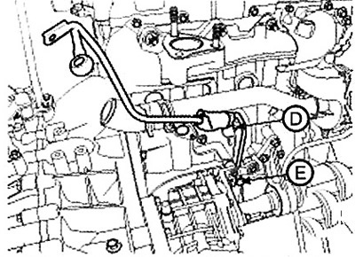
11. Remove the turbocharger oil supply pipe (A).
Note: Tightening torque:
- Bolt (B): 11.8 - 17.7 Nm.
- Bolt (C): 9.8 - 11.8 Nm.
- Bolts (D, E): 19.6 - 26.5 Nm.
 |
 |
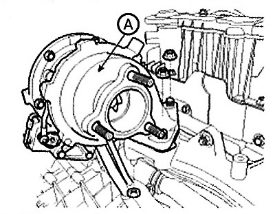
12. Remove the turbocharger assembly (A).
Note: Tightening torque: 49.0-68.6 Nm.
13. Remove the exhaust manifold heat shield (A).
Note: Tightening torque: 9.8-11.8 Nm.
14. Remove the exhaust manifold (A) with the gasket (B).
Note: Tightening torque: 39.2-44.1 Nm.
When installing the bushings, the larger part should be facing towards the cylinder block.
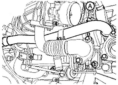
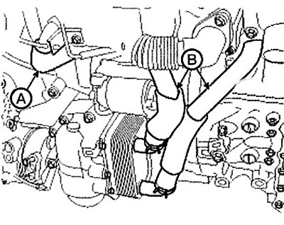
15. Disconnect the coolant inlet hose (A).
16. Disconnect the exhaust gas recirculation (EGR) vacuum pipe (A).
17. Remove the air control valve (A).
Note: Tightening torque: 8.8-10.8 Nm.
18. Remove the coolant outlet pipe (A).
Note: Tightening torque: 7.8-11.8 Nm.
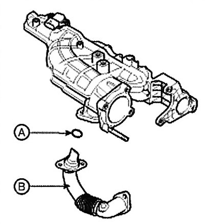
19. Remove the exhaust gas recirculation (EGR) pipe assembly (A).
Note:
Tightening torque:
- Bolts (B): 19.6-23.5 Nm.
- Bolts (C): 9.8-11.8 Nm.
Before installing the exhaust gas recirculation (EGR) pipe (B), be sure to install the O-ring (A) into the intake manifold.
Caution: If the O-ring is inserted into the intake manifold when installing the EGR pipe, it may be damaged, resulting in exhaust gas leakage.
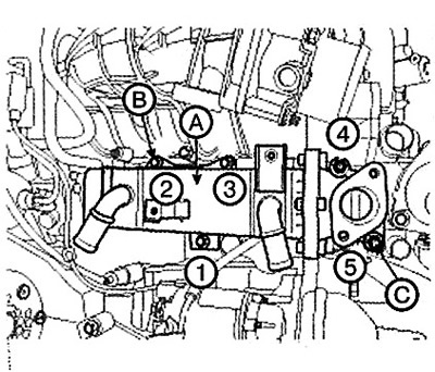
20. Disconnect the EGR cooler hose (A) and oil cooler hoses (B).
The original text is located on the portal HYUNDAIBOOK.ru
21. Remove the exhaust gas recirculation (EGR) cooler (A).
Note: Tightening torque:
- Bolt (B): 9.8 - 11.8 Nm.
- Nut (C): 19.6 - 26.5 Nm.
When installing the EGR cooler, pre-tighten the bolts and nuts, then tighten them to the specified torque in the specified order.
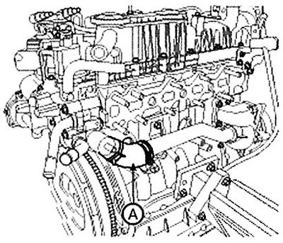
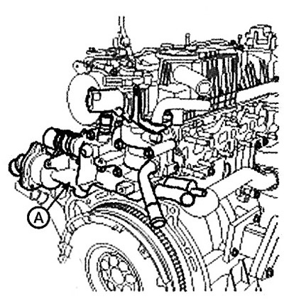
22. Remove the thermostat housing and EGR assembly (A).
Note: Tightening torque: 19.6-24.5 Nm.
23. Installation is carried out in the reverse order of removal.