
The location of the airbag electronic control unit is shown in the figure.
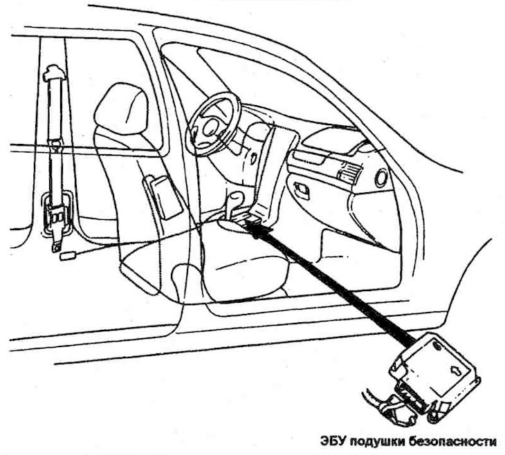
The airbag control unit fills the airbags based on a signal from the frontal impact sensor built into the airbags.
1. DC-DC converter: The DC-DC converter in the power supply circuit includes a step-up converter and a step-down converter, which supplies voltage to the four ignition circuits and the internal working voltage. When the internal working voltage falls below a certain limit, the system will be reset to its original state.
2. Impact sensor/safety sensor: The impact sensor/safety sensor, integrated into the airbag ignition circuit, serves to activate the airbag circuits under all deployment conditions and to maintain the ignition circuits in a non-activated state under normal driving conditions. The impact sensor is designed as a two-contact electromechanical switch, the contacts of which are closed by negative acceleration exceeding a certain threshold value.
3. Backup power supply: The airbag control unit has a backup power supply that ensures that the airbags are activated for a short period of time if the voltage in the vehicle electrical system is insufficient or if the power supply is interrupted in the event of a frontal impact.
4. Detection of malfunctions: When the ignition is on, the PB ECU constantly monitors the system status and detects possible malfunctions. Malfunctions are displayed using the Hi-Scan device as diagnostic trouble codes.
5. Malfunction Indicator Lamp (MIL): When a malfunction is detected, the ECU warns the driver by illuminating the indicator lamp in the instrument cluster. The MIL is the primary means of alerting the driver to malfunctions in the airbag system. When the ignition is first turned on, the indicator lamp flashes six times, indicating a malfunction in the lamp itself and the ECU.
6. Recording fault codes: When a fault occurs in the system, the ECU records a diagnostic code in its memory, which can only be deleted using the Hi-Scan device.
7. Using the data line connector located under the instrument panel on the driver's side, the data stored in the ECU memory is transmitted to an external device, in particular to the Hi-Scan device.
8. When only the seat belt pretensioners are activated.
9. Door lock unlocking output. This output is used to unlock the door locks upon impact. The signal from this output is 0-200 μA in the off mode and 200 mA in the on mode. When the unlocking command is issued, the switch closes for 200 ms.