
Note: the procedure for checking and adjusting the clutch pedal is described in chapter «Maintenance».
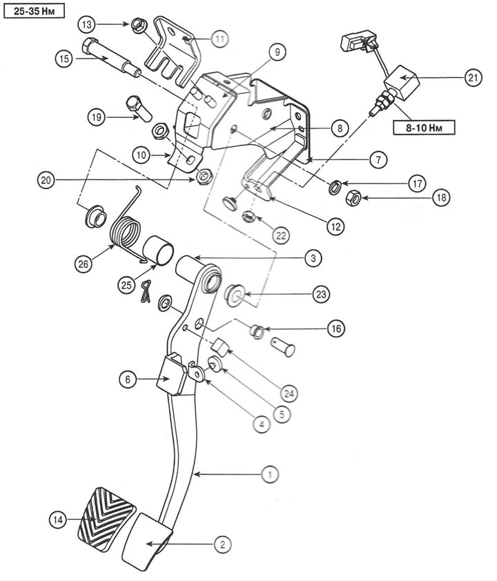
1. Clutch lever; 2. Pedal platform; 3. Pivot pin; 4. Bracket; 5. Pedal stop damper; 6. Lever bracket; 7. Support panel; 8. Pedal bracket; 9. Bracket stop and switch; 10. Bolt; 11. Support bracket; 12. Stop bracket; 13. Nut; 14. Pedal pad; 15. A bolt of fastening of a pedal to an arm; 16. Sleeve; 17. Washer; 18. Nut; 19. Bolt for adjusting the upper position of the pedal; 20. Nut; 21. Clutch switch; 22. Switch nut; 23. Sleeve; 24. Stop of the brake pedal; 25. Support sleeve return spring; 26. Return spring.
Withdrawal
1. Remove the cotter pin with washer, remove the hinge pin and disconnect the master cylinder pusher from the pedal.
Note: Apply SAE J310a, NLGI NO.1 grease to pivot pin and pedal bush before installation.
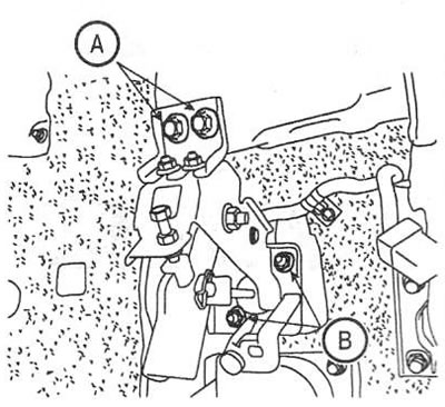
2. Loosen the screws (A) and nuts (IN) mounting bracket assembly. Tightening torque: 10-17 Nm.
Examination
3. Check all parts of the clutch pedal for damage and replace if necessary.
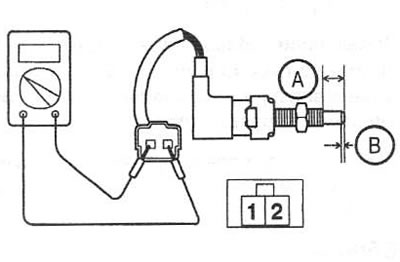
4. Remove the clutch switch and check the circuit between the connector pins. When pressed, the circuit must be closed, and when released, it must be open.
5. Check the opening travel and full travel of the switch plunger. Rated value: 12.0±0.3mm (shutdown stroke); 2.0±0.3mm (full speed).
Installation
6. Installation is carried out in reverse order.
7. Bleed the clutch