


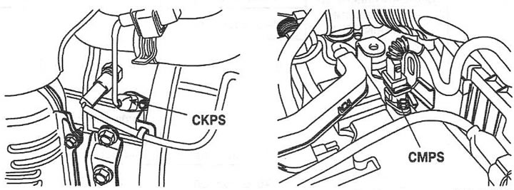
Checking the signal shape
The figure shows the shapes of typical sensor signals at the engine crankshaft idle speed.

Checking CMPS Wiring
With the ignition on, measure the voltage between the contacts of the wire part of the connector and the ground.
| Circuit under test | Nominal voltage |
| Contact 1 - "ground" | B+ |
| Contact 2 - "ground" | 12 V |
| Contact 3 - "ground" | 0 B |
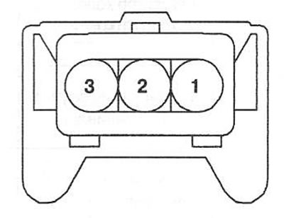
1. Power supply from the main relay
2. Sensor signal
3. Sensor "mass"
Checking the CKPS wiring
With the ignition on, measure the voltage between the contacts of the wire part of the connector and the ground.
| Circuit under test | Nominal voltage |
| Contact 1 - "ground" | Approximately 2.5 V |
| Contact 2 - "ground" |
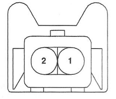
1. Signal B of the sensor
2. Sensor signal A