
Removal and installation
Vehicles without airbag
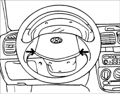
1. Remove the horn button and steering wheel.
2. Remove the upper and lower steering column covers.
3. Loosen the screws and remove the multifunction switch.
4. Installation is carried out in the reverse order of removal.
Cars with airbag
When removing the multi-function switch on vehicles equipped with an airbag, be careful and comply with the following conditions.
Warning! Do not disassemble any component of the SRS. Disassembly of components may disable the safety system.
Warning! Avoid contact with solvents or cleaning agents on the airbag.
Transport the airbag separately, bag side up.
Warning! If any SRS component has been dropped or has cracks, dents, or other defects in the housing, bracket, or connector, replace it with new ones.
Warning! When transporting, do not put your hands on the airbag.
Warning! Do not heat the airbag unit to temperatures above 93°C.
Warning! After deploying the airbag, replace the sensor coil spring with a new one.
Warning! Before installing the air bag sensor coil spring, align the mark and the sensor spring neutral pointer with the front wheels set to drive straight ahead. If the coil spring mark is not aligned properly, the steering wheel will not be able to turn fully or the coil spring wire will be damaged, preventing the SRS from working properly.
Order of execution
1. Disconnect the wire from the negative battery terminal.
Warning! Before servicing the airbag system, make sure that at least 30 seconds have passed after the ignition is turned off and the wire is disconnected from the negative terminal of the battery.
Warning! The airbag system is equipped with an emergency power source that allows the airbags to deploy if the battery wires are disconnected in an accident.
2. Turn out bolts of fastening of an airbag. Disconnect the horn and airbag connectors and remove the airbag unit.
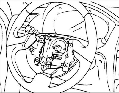
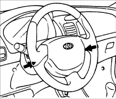
3. Remove the steering wheel.
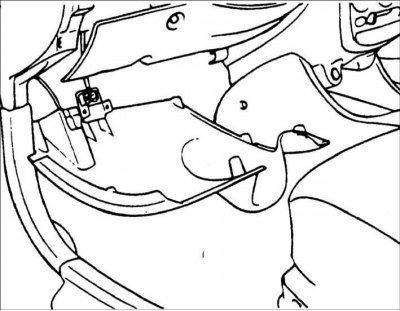
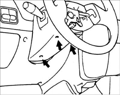
4. Remove the driver's knee support.
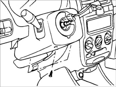
5. Turn out screws and remove the top and lower casings of a steering column.
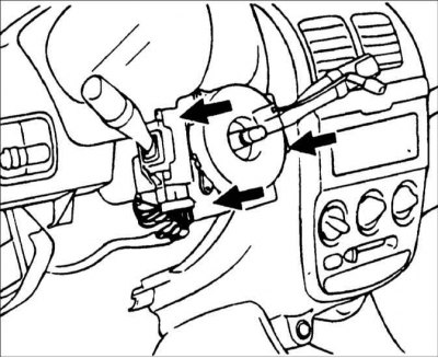
6. Loosen the screws and remove the multifunction switch.
7. Installation is carried out in the reverse order of removal.
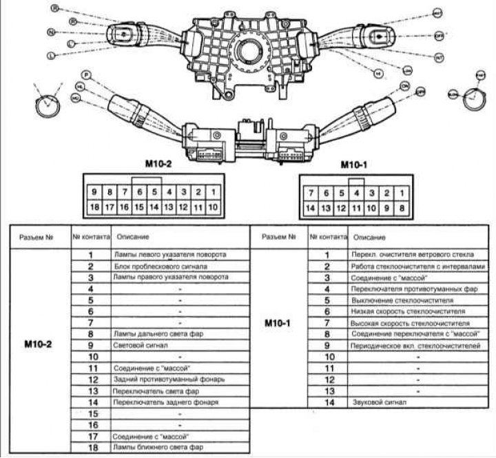
Examination
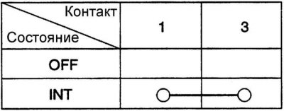
With the multi-function switch in each position, check the continuity between the corresponding pins of the connectors. If the conductivity is not correct, replace the multifunction switch.
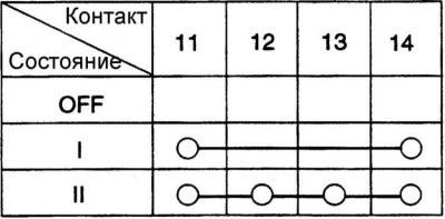
Light switch (connector M10-2)
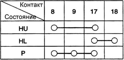
Headlight switch (connector M10-2)
HU: high beam
HL: dipped beam
P: position lighting
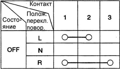
turn switch (connector M10-2)
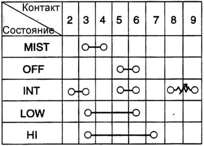
Wiper switch (connector M10-1)
Washer switch (connector M10-1)