
Flat feeler gauges
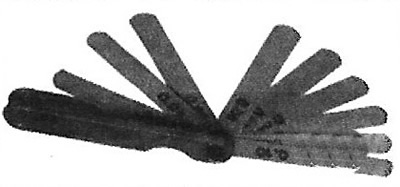
Feeler gauges (see figure) are a set of plates of a certain thickness with corresponding markings, used to measure various clearances. Also, feeler gauges can be used, for example, to measure axial play where the use of a dial indicator (see below) is difficult.
The set of flat feeler gauges must be protected from excessive force and impacts so that the feeler gauge plates are not bent or damaged. The surface of the flat feeler gauges must be kept clean and covered with a thin layer of oil to prevent corrosion.
When measuring the gap, it is necessary to select a flat feeler gauge that will fit with little resistance between the two parts. It is recommended to have two sets of flat feeler gauges to ensure measurement accuracy.
Micrometers
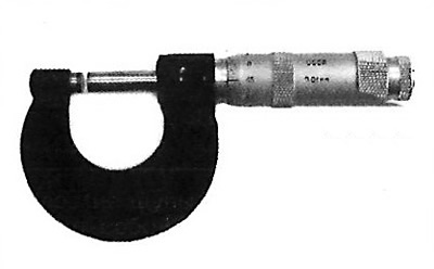
A micrometer is a device designed for measuring linear dimensions using the absolute contact method in the area of small dimensions with high accuracy (from 0.01 to 0.001 mm), the conversion mechanism of which is a screw-nut micropair.
It is necessary to keep the micrometer clean. Be careful not to drop the micrometer, as its bracket may become deformed, which will lead to inaccurate measurements.
The operation of the micrometer is based on the movement of the screw along the axis when it rotates in a fixed nut. The movement is proportional to the angle of rotation of the screw around the axis. Full turns are counted on the scale applied to the stem of the micrometer, and fractions of a turn - on the circular scale applied to the drum. The optimal movement of the screw in the nut is only a length of no more than 25 mm due to the difficulty of manufacturing a screw with an accurate pitch over a greater length. Therefore, the micrometer is made in several standard sizes for measuring lengths from 0 to 25 mm, from 25 to 50 mm, etc. For micrometers with measurement limits from 0 to 25 mm with closed measuring planes of the heel and the micrometer screw, the zero mark of the drum scale must exactly coincide with the longitudinal mark on the stem, and the beveled edge of the drum - with the zero mark of the stem scale. To measure lengths greater than 25 mm, a micrometer with replaceable heels is used; setting such micrometers to zero is done using a setting measure applied to the micrometer or end measures. The item being measured is clamped between the measuring planes of the micrometer. Usually the pitch of the screw is 0.5 or 1 mm and, accordingly, the scale on the stem has a division value of 0.5 or 1 mm, and 50 or 100 divisions are applied to the drum to obtain a reading of 0.01 mm. This reading value is the most common, but there are micrometers with a reading of 0.005, 0.002 and 0.001 mm. A constant axial force when the screw contacts the item is provided by a friction device - a ratchet. When the measuring surfaces of the micrometer are in close contact with the surface of the item being measured, the ratchet begins to turn with a slight crack, and the rotation of the microscrew should stop after three clicks.
Calipers
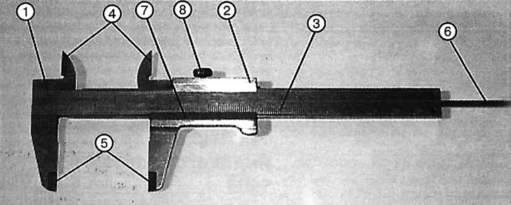
1. Barbell.
2. Movable frame.
3. Barbell scale.
4. Sponges for internal measurements.
5. Sponges for external measurements.
6. Depth gauge ruler.
7. Nonius.
8. Frame clamp screw
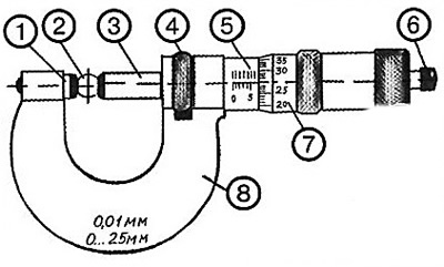
1. Heel. 2. Object of measurement. 3. Spindle. 4. Wheel. 5. Measuring scale (in mm). 6. Ratchet.
7. Drum vernier. 8. Clamp.
When taking measurements, the object (2) is clamped between the heel and the micrometer screw (3). On the surface of the stem there are two line scales, offset relative to each other by 0.5 mm, and having a division value of 1 mm. The drum (7) rotates around the circular scale, which is also located on the bevel of the drum. The micrometer screw can be fixed in any position. The screw is equipped with a ratchet mechanism to ensure the constancy of the measuring pressure.
1. The object is placed between the heel and the micrometer screw, while rotating the drum, the spindle is set to the approximate size of the object.
2. The spindle is carefully moved until it comes into contact with the object being measured.
3. The size in mm is determined using the drum vernier, which corresponds to the horizontal index line of the stem scale.
4. The overall size of the measured object is determined.
Note: When in contact with the measured object, do not tighten the spindle by rotating the drum sleeve by hand, this may cause the micrometer to break. For more accurate measurement, make sure that the object is well secured.
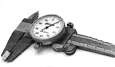
A caliper is a universal tool designed for high-precision measurements of external and internal dimensions. In addition, a caliper can be used to determine the depth of holes and protrusions.
The measuring jaws of the caliper can also be used to measure the parallelism of the sides of workpieces. Publishing House "Monolith"
The calipers have measurement ranges of 0-125 mm (ШЦ-1), 0-160 mm (ШЦ-2) and 0-400 mm (ШЦ-3).
The most frequently used caliper is the ШЦ-1.
To measure external dimensions and check parallelism, the main measuring jaws of the tool are used, and to measure internal dimensions and mark out, auxiliary pointed jaws are used.
Using a depth gauge, determine the depth of holes and protrusions.
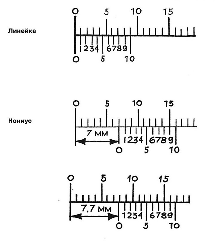
The basis of the caliper device is a ruler with divisions (rod) and an auxiliary scale-vernier, which moves along the main ruler-rod. With the help of this auxiliary scale, it is possible to count off the division fractions of the main scale.
The operating principle of the vernier is based on the difference in the division intervals of the main scale and the vernier scale. This difference is equal to the division value of the vernier, and the number of divisions depends on the division value.
If the scale division interval is 1 mm, and the vernier division interval is 0.9 mm, then the vernier division value is 0.1 mm.
Thus, if you combine the zero division of the vernier with the zero division of the main scale of the caliper, then the first division of the vernier will "lag" behind the first division of the main scale by the amount of the difference in the scale intervals, i.e. by 0.1 mm, the second division by 0.2 mm, etc.
The tenth division of the vernier, having shifted by 1 mm, coincides with the ninth division of the main scale of the rod, that is, if the division value of 1 mm is divided by the number of divisions of the vernier (by 10), we get 0.1 mm (see Fig.)
Example:
If the zero mark of the vernier coincides with any mark on the ruler, then this/the division indicates the size in whole millimeters.
If the zero mark of the vernier does not coincide with the mark on the main scale, then the division on the ruler closest to the left shows a whole number of millimeters, and tenths are counted according to the vernier.
To the whole number of millimetres are added as many tenths of a millimetre as there are vernier strokes until any vernier stroke completely coincides with one of the ruler strokes. The figure shows an example of reading 7 mm, and 7.7 mm.
Some calipers are equipped with a dial indicator. The dial indicator allows you to adjust the zero setting and control tolerances.
During and after work, wipe the caliper with a napkin soaked in an aqueous alkaline solution, then dry with a clean napkin. After work, cover the surfaces of the caliper with a thin layer of any technical oil and put it in a case. Avoid rough impacts or falls during operation to avoid bending the rod and other damage, scratches on the measuring surfaces, friction of the measuring surfaces against the controlled part.
Dial type indicator
The dial indicator is designed to measure linear dimensions using absolute and relative methods, determine the magnitude of deviations from a given geometric shape and the relative position of surfaces. Indicators with a measurement range of 0-2 mm are available in two versions:
- ICH - with the movement of the measuring rod parallel to the scale;
- IT - with the movement of the measuring rod perpendicular to the scale.
The indicators are attached either to a connecting sleeve with a diameter of 8h7, or to a 5 mm thick eye with a connecting hole with a diameter of 5 mm.
The use of the dial indicator is very diverse, so it is not described here. Specific cases of using the device are described in the repair manual (for example, measuring the axial play of the engine crankshaft, measuring the runout of the brake disc, etc.).
Bore gauge
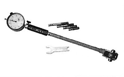
The bore gauge is designed to measure the internal dimensions of parts (for example, the diameter of a cylinder bore, the width of grooves, etc.).
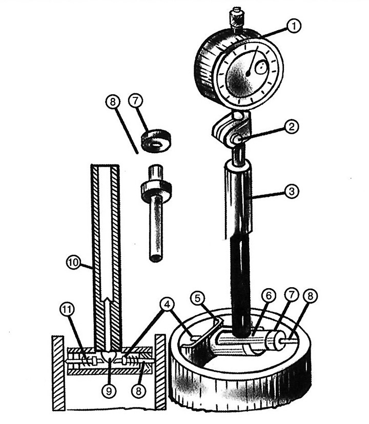
1. Hour type indicator.
2. Screw.
3. Handle.
4. Engine.
5. Centering bridge.
6. Tee.
7. Nut.
8. Measuring rod.
9. Fungus.
10. Rod.
11. Spiral spring.
The device has a guide bushing (5), in the upper part of which a dial indicator (1) is installed, secured with a screw (2). Inside the bushing there is a long rod, which contacts a short rod (10), resting against the mushroom (9) of the tee (6) of the bore gauge head. In the tee there is an engine (4) and a replaceable measuring rod (8), secured in the tee with a nut (7). On the side of the movable pin on the tee there is a centering bridge 5, which serves to set the indicator head according to the diameter of the hole. When measuring holes, the engine (4) with a spiral spring (11) presses on the mushroom (9) and through the rod (10) transmits movement to the long rod to the indicator.
The deviation of the size is determined by the movement of the indicator arrow. Before measuring, the bore gauge is set to the nominal size on the ring or block of tiles.
Indicator bore gauges are produced with measurement limits: 6-10; 10-18; 18-35; 35-50; 50-100; 100- 160; 160-250; 250-450 mm. For measurement, replaceable washers and rods are attached to the bore gauge, differing from each other by 1 or 5 mm (depending on the measurement limit). The washers are installed in the hole of the head tee.