
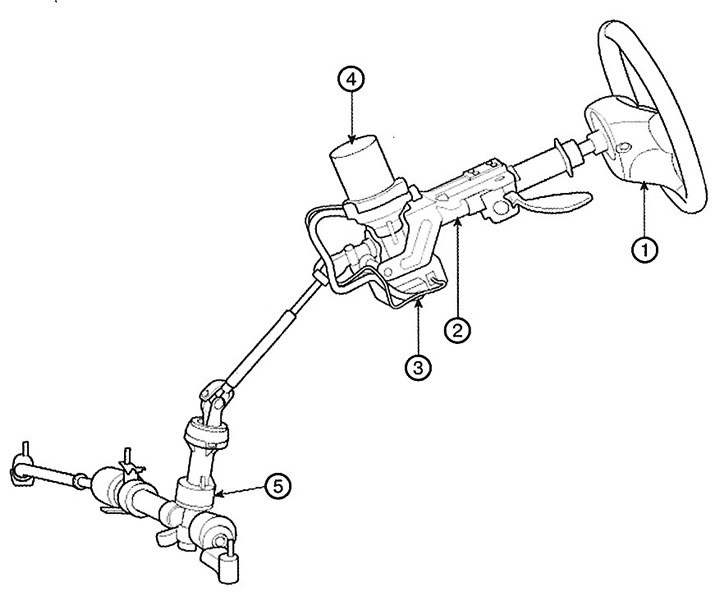
1. Steering wheel
2. Steering column
3. Control unit
4. Motor
5. Steering mechanism
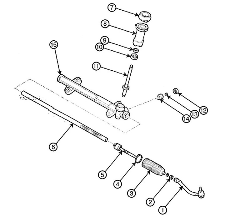
1. Tie rod end
2. Lock nut
3. Dust cover
4. Dust cover clamp
5. Steering rod
6. Rail
7. Dust seal
8. Dust cover
9. Seal
10. Gear plug
11. Gear assembly
12. Rack stop plug
13. Stop spring
14. Rack stop
15. Rack housing
Replacement
1. Remove the front wheel.
Note: Tightening torque: 88.3-107.9 Nm.
The original text is published on the website HyundaiBook.ru
Caution: Be careful not to damage the hub bolts when removing the front wheel.
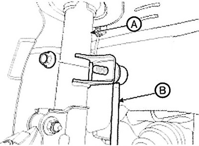
2. Loosen the nut and disconnect the stabilizer link (B) from the front strut (A).
Note: Tightening torque: 98.1 - 117.7 Nm.
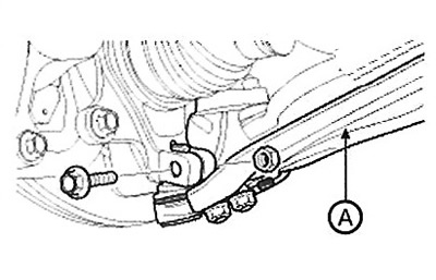
3. Remove the cotter pin and castle nut, then disconnect the tie rod end (A) from the steering knuckle.
Note: Tightening torque: 34.3-44.1 Nm.
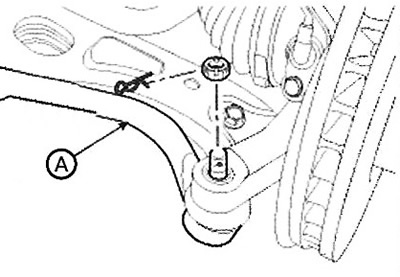
4. Loosen the bolts and nuts and remove the lower arm (A).
Note: Tightening torque: 98.1 - 117.7 Nm.
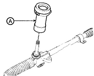
5. Loosen the nut and remove the dust cover (A).
6. Loosen the bolt (A), then disconnect the universal joint from the steering gear pinion.
Note: Tightening torque: 29.4 - 34.3 Nm.
Caution: To avoid damaging the inner wire of the contact disc when handling the steering wheel, fix the steering wheel in the straight-ahead position.

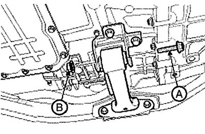
7. Remove the bolt (A) and nut (B), then remove the rear roller stop.
Note: Tightening torque: 107.9 - 127.5 Nm.
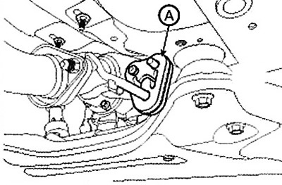
8. Disconnect the rubber mount (A) of the muffler.
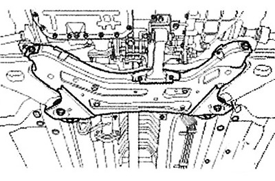
9. Unscrew the bolts and nuts and remove the subframe.
Note: Tightening torque: 176.5 - 196.1 Nm.
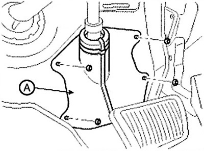
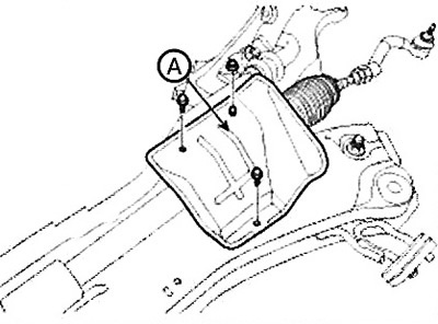
10. Unscrew the bolt and nut and remove the protection (A).
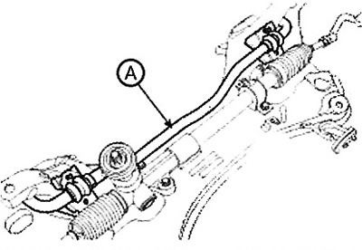
11. Loosen the bolt and remove the stabilizer (A) from the subframe.
Note: Tightening torque: 44.1 - 53.9 Nm.
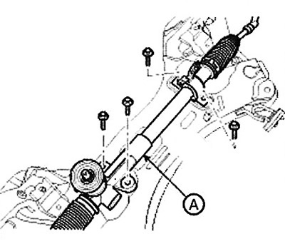
12. Loosen the bolt and remove the steering gear (A).
Note: Tightening torque: 58.8 - 78.5 Nm.
13. Installation is carried out in reverse order.
Disassembly and assembly
1. Remove the dust seal and boot (A) from the gear housing.
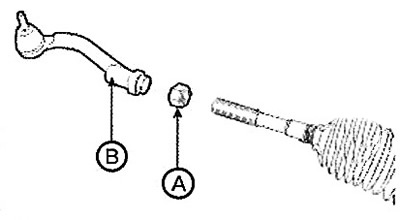
2. Loosen the lock nut, then remove the tie rod end (B) and loosen the lock nut (A).
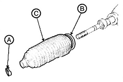
3. Remove the clamp (A) and the boot clamp (B), then remove the boot (C) from the steering rod.
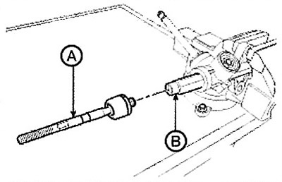
4. Loosen the inner ball joint of the steering rod and disconnect the rod (B) from the toothed rack (A).
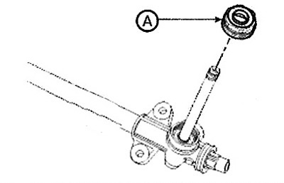
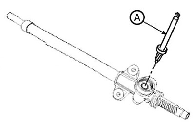
5. Remove the plug (A) from the gear housing.
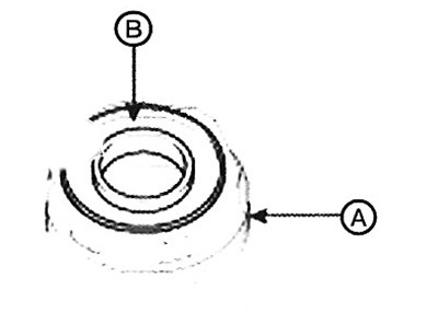
6. Remove the seal (B) from the plug (A).
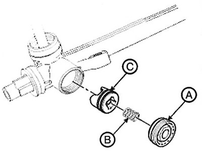
7. Remove the stop plug (A) and spring (B), then remove the rack stop (C).
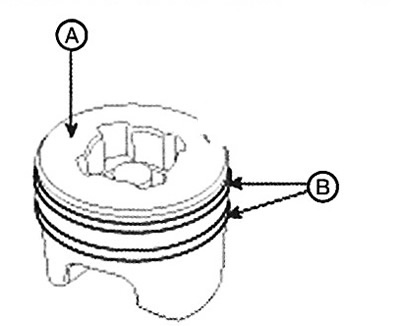
8. Remove the sealing ring (B) from the stop (A).
9. Remove the gear (A) from the housing.
10. Remove the toothed rack (A) from the housing.
11. Assembly is carried out in the reverse order of disassembly.
Checking the technical condition
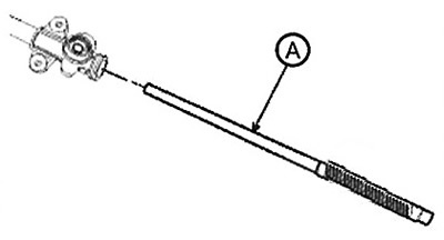
1. Rack and pinion
A. Check the rack for damage.
B. Check the rack for deformation and curvature.
2. Gear
A. Check the gear for damage.
B. Check the oil seal for damage.
3. Check the inner surfaces of the rack housing for damage.