
Order of execution
1. Raise the vehicle and release the parking brake.
2. Disconnect the connector from the HECU.
Warning! Be sure to release the double connector lock and connect the test probe to the connector on the harness side.
3. Connect a voltmeter or oscilloscope to the connector pins and measure the voltage generated by the sensor when the wheel rotates.
Connector pins
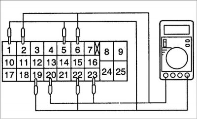
1 and 2: front left sensor
19 and 20: front right sensor
5 and 6: rear left sensor
22 and 23: rear right sensor
Output voltage when measured with an oscilloscope: 150 mV.
Withdrawal
Front wheel speed sensor
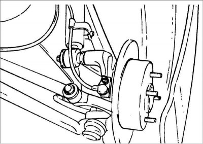
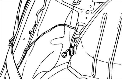
1. Turn out a bolt of fastening of the forward sensor of frequency of rotation of a wheel.
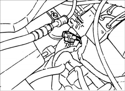
2. Disconnect the connector and remove the front wheel speed sensor.
Rear wheel speed sensor
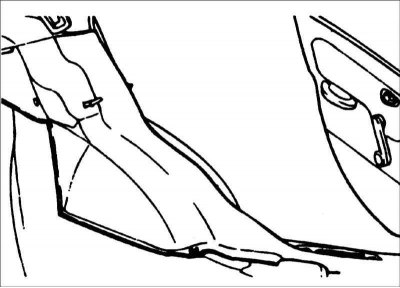
1. Remove the rear seat cushion.
2. Remove an upholstery of a back rack.
3. Remove the rear wheel.
4. Disconnect the connector and remove the rear wheel speed sensor.
Examination
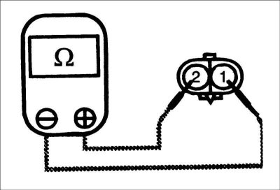
1. Measure the resistance of the wheel speed sensor between the connector terminals.
Resistance:
- Front sensor: 1275-1495 ohms
- Rear sensor: 1275-1495 ohms
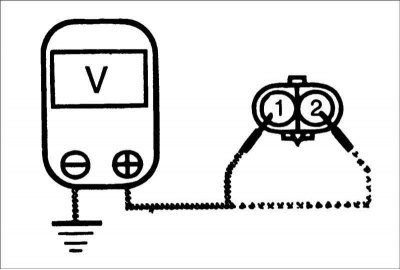
2. Connect a voltmeter to the sensor connector terminals, measure the voltage generated by the sensor when the wheel rotates.
Attention! Switch the voltmeter to measure AC voltage.