


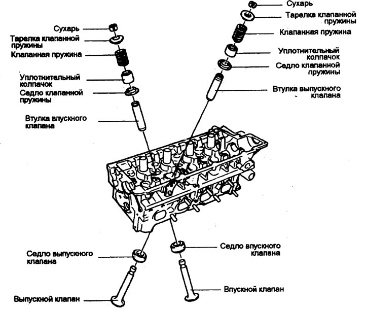
Removal
1. Using a special tool to compress the valve springs (09222-28000, 09222-29000), remove the cracker. Next, remove the upper valve spring retainer, valve spring, lower retainer and valve.
Note: Keep these parts in the order in which they should be installed in their original locations.
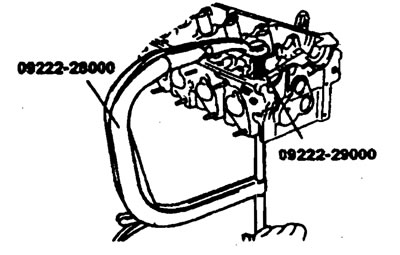
2. Remove the sealing cap with pliers using a special tool (09222-29000), and throw it away.
Note: Do not reuse sealing caps.
Examination
Valves
1. Using a wire brush, thoroughly clean the valve.
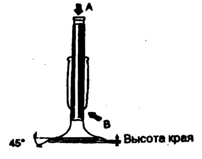
2. Check each valve for wear, damage and destruction of the head and stem in the area
 . Repair or correct if necessary.
If the end
 the rod is worn out, restore its surface if necessary. Also restore the surface of the valve working chamfer. If the valve edge height is less than the permissible limit, replace the valve.
Valve edge height
Nominal size
- Inlet valve - 1.1 mm
- Exhaust valve - 1.4 mm
Maximum size
- Inlet valve - 0.8 mm
- Exhaust valve - 1.0 mm
Valve springs
1. Check the length of the spring in the assembled state and its extension. If the permissible limits are exceeded, replace the spring.
2. Check the parallelism of the ends of each spring. If the non-parallelism of the ends exceeds the established limits, replace the spring.
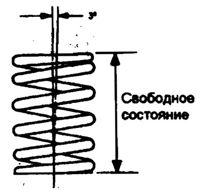
Valve springs
Nominal value
- Height in free state - 46.07 mm
- Load - height - 25.5 kg/37 mm - 57.3 kg/28 mm
- Deviation from parallelism is 3° or less.
Valve bushings
Check the clearance between the valve stem and the bushing. If the clearance exceeds the specified limits, replace the valve bushing with the next size bushing.
Clearance between valve stem and sleeve.
Nominal size
- Inlet valve - 0.020-0.050 mm
- Exhaust valve - 0.050-0.085 mm
Maximum size
- Inlet valve - 0.1 mm
- Exhaust valve - 0.15 mm
Oversized valve bushings
| Size, mm | Size designation | Cylinder head hole size, mm |
| 0.05 O.S. | 5 | 11.05-11.068 |
| 0.25 O.S. | 25 | 11.25-11.268 |
| 0.50 O.S. | 50 | 11.50-11.518 |
OS - Increased size
Valve seat
Check the valve seat for signs of overheating and proper contact with the valve seat face. Repair or replace the valve seat if necessary. Before repairing the seat, check the valve bushing for wear. If the bushing is worn, replace it and then repair the seat. Repair the valve seat using a valve seat grinder or milling cutter.
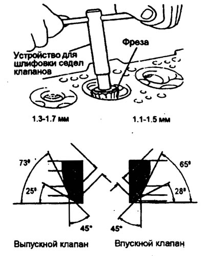
Valve seat replacement procedure
1. The valve seat worn beyond the permissible limits should be replaced at normal temperature after cutting off most of the seat wall with a valve seat grinding device as shown in the figure "A".
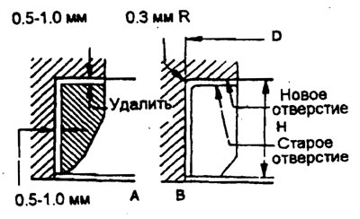
Oversized saddle
| Name | Size, mm | Size designation | Seat height, N·mm | Inner diameter of the hole in the cylinder head, mm | |
| Intake valve seat | 1.6 l | 0.3 O.S. 0.6 O.S. | 30.60 | 8.2-8.4 8.S-8.7 | 31.30-31.325 31.60-31.625 |
| 1.8 l | 0.3 O.S. 0.6 O.S. | 30.60 | 7.7-7.9 8.0-8.2 | 33.30-33.325 33.60-33.625 | |
| Exhaust valve seat | 1.6 l | 0.3 O.S. 0.6 O.S. | 30.60 | 8.7-8.9 9.0-9.2 | 26.80-26.825 27.10-33.625 |
| 1.8 l | 0.3 O.S. 0.6 O.S. | 30.60 | 8.2-8.4 8.S-8.7 | 28.80-28.821 29.10-29.121 | |
OS - Increased size
Valve Bushing Replacement Procedure
The valve sleeve is installed using a press fit. Using a valve bushing installation device (09221-22000) or the appropriate tool, replace the valve sleeve in the following order.
1. Using the valve sleeve installer pusher, push the valve sleeve towards the cylinder block using a press.
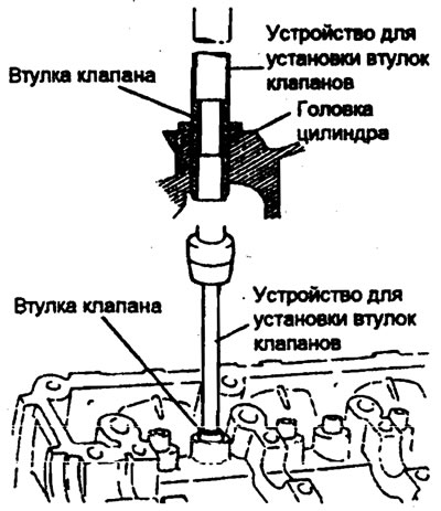
2. Machine the valve bushing hole in the cylinder head to fit the increased size of the new valve bushing.
3. Using a valve sleeve installer or appropriate tool, press the valve sleeve into a press fit. Using the valve bushing installation device, it is possible to press the valve bushing to a specified height. The valve sleeve must be installed from the top of the cylinder head. Please note that the intake and exhaust valve bushings are different lengths (42.7 mm for intake valve and 39.1 mm for exhaust valve).
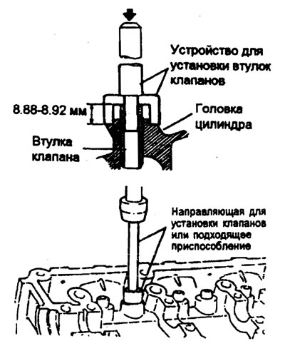
4. After installing the bushings, insert new valves into them and check the clearance between them.
5. Each time the bushings are replaced, check the nature of the valve contact with the seat and, if necessary, restore the seat surface.
Installation
Note:
- 1) Clean all parts before assembly.
- 2) Use motor oil to lubricate rotating and sliding parts.
1. After installing the lower spring plate, press the sealing cap onto the valve sleeve. Install the cap by gently rotating the valve cap installer (09222-22000).
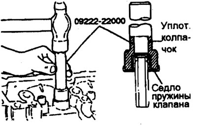
The sealing cap is installed in the required position using a special tool. If it is not positioned correctly, the protrusion of its inner hole may be eccentric and oil may leak into the valve sleeve. Do not rotate the cap during installation. Do not use old sealing caps.
2. Apply engine oil to each valve. Insert the valves into the bushings, do not force the valve stem through the sealing cap. After installation, make sure the valve moves easily.
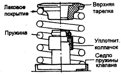
3. Install the valve springs on their upper plates. Valve springs should be installed with the varnished side facing the top plate.
4. Using a valve spring compressor (09222-28000,09222-29000), compress the spring. Be careful not to deform the top of the plate with the sealing cap. Then install the crackers. After installing the valves, make sure the crackers are installed correctly.
5. Install the cylinder head.