
Contents: Removal ⇓ Installation ⇓
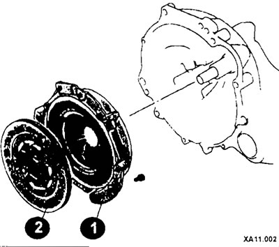
Clutch elements
1 - leading (pressure) clutch disc;
2 - driven clutch disc.
Removal
Remove the gearbox.
Mark the position of the drive disc on the engine flywheel.
By inserting a screwdriver or metal rod into the teeth of the ring gear, lock the engine flywheel.
Release the springs of the drive disk by unscrewing the bolts of the driven disk diagonally one by one, 1-2 turns each time. •Then unscrew the bolts of the drive disk.
Wipe the engine flywheel with gasoline.
The driven clutch disc must not be cleaned. Oil residues must not be removed with detergents.
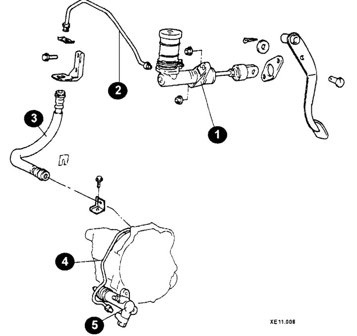
Clutch drive elements (models before 2000.)
1 - clutch master cylinder;
2, 4 - hydraulic tube;
3 - hose;
5 - clutch slave cylinder.
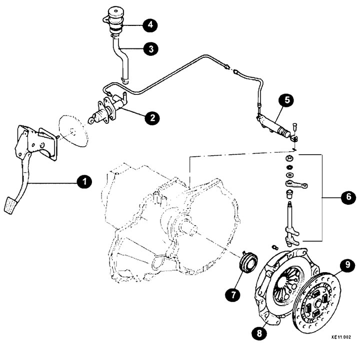
Clutch drive elements (models since 2000.)
1 - pedal;
2 - clutch master cylinder;
3 - expansion tank hose;
4 - expansion tank;
5 - clutch slave cylinder;
6 - clutch shift fork elements;
7 - release bearing;
8 - clutch drive disc;
9 - driven clutch disc.
Installation
Sand the driven disk and engine flywheel with very fine sandpaper.
Original version of the article on the website [HyundaiBook]
Remove any corrosion from the splined joint of the driven disk and apply a small amount of molybdenum-containing grease.
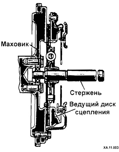
Place the driven and leading clutch discs onto the flywheel. In this case, the long side of the driven disk hub should be located on the outside, i.e. on the gearbox side. Center the driven disk relative to the driving disk by eye. But it is better to use a special rod or an old gearbox drive shaft for this.
If the old clutch drive disc is reinstalled, the markings made during removal must be observed.
Tighten the clutch mounting screws crosswise in several stages. The final tightening torque should be 20 Nm. While tightening the bolts, insert and remove the centering rod (or shaft) to check the alignment.
Remove the locking tool from the flywheel ring gear.
If removed, install the release bearing, applying grease to the indicated areas (arrows).
