
Note: the device and location of individual elements of the toxicity reduction system may differ from those shown depending on the sales market and vehicle equipment.
Location of elements of the toxicity reduction system
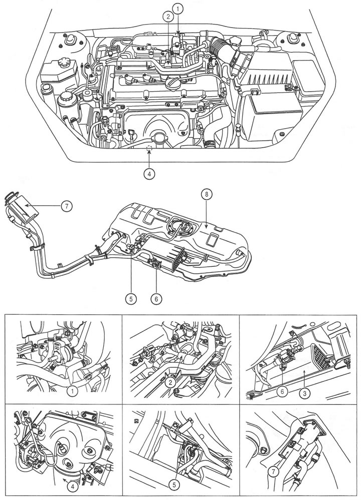
1. Canister purge valve
2. Crankcase ventilation valve
3. Carbon absorber
4. Catalytic Converter
5. Fuel tank pressure sensor
6. Absorber shut-off valve
7. Fuel tank air filter
8. Fuel tank
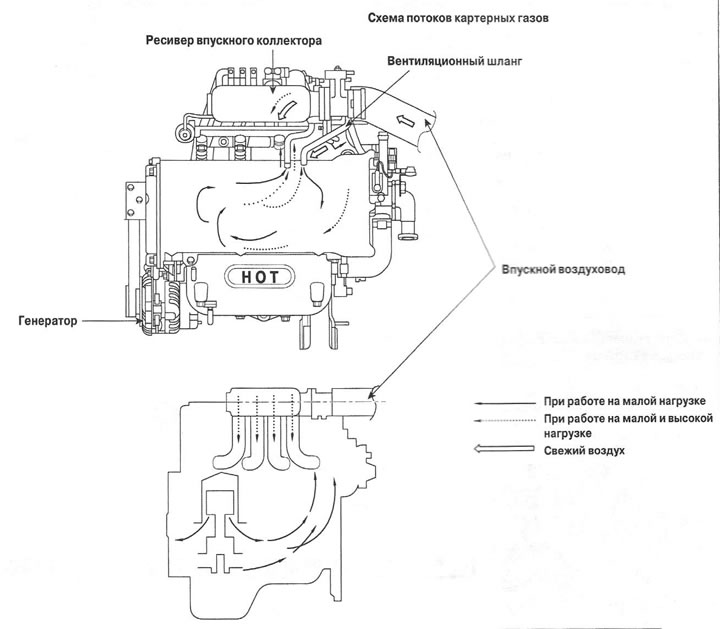
Scheme of crankcase gas flows
Evaporative Emission System Schematic
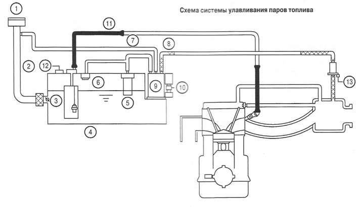
1. Filler cap
2. Filler neck
3. Filler stop valve
4. Fuel tank
5. Vent valve
6. Fuel cut-off valve
7. Ventilation hose
8. Canister Purge Hose
9. Carbon absorber
10. Fuel line
12. Fuel tank pressure sensor
13. Absorber purge valve