
Contents: Removal ⇓ Installation ⇓
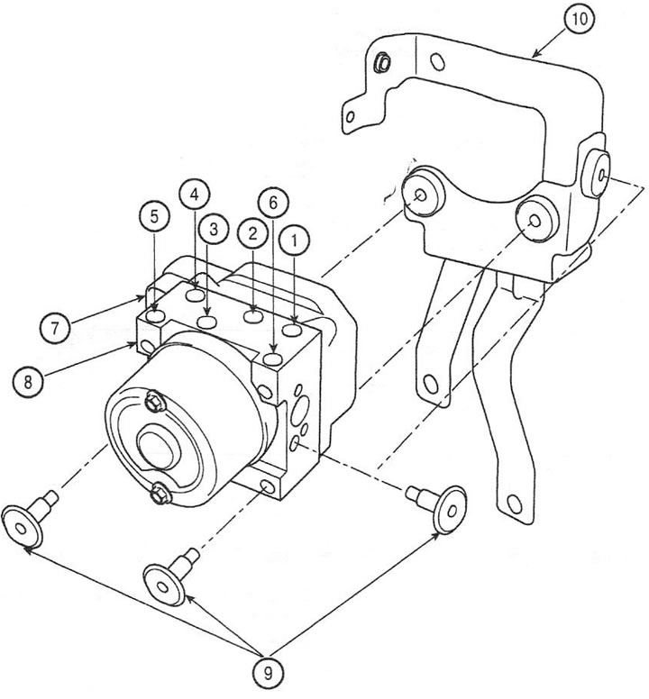
1. Exit to the anterior right branch; 2. Exit to the rear left branch; 3. Exit to the rear right branch; 4. Exit to the anterior left branch; 5. Input from the primary circuit of the GHz; 6. Input from the secondary circuit of the GTZ; 7. Control unit connector; 8. Electronic-hydraulic control unit; 9. Screw; 10. Bracket
Removal
1. Turn off the ignition.
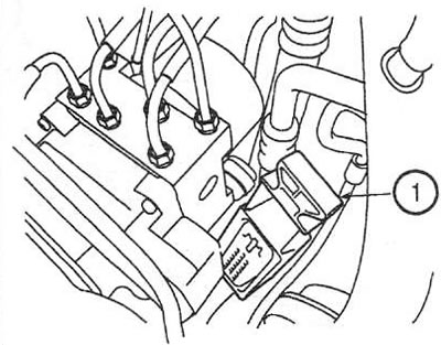
2. Remove the retainer (1) and disconnect the electronic control unit connector.
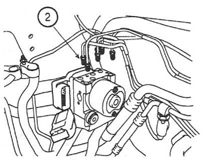
3. Disconnect the brake pipes from the hydraulic unit by unscrewing the union nuts (2) counterclockwise. Tightening torque: 12-16 Nm.
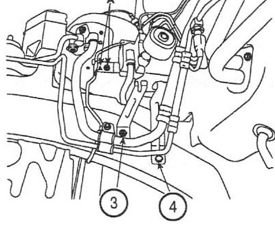
4. Unscrew the three screws (3), nut (4) and remove the hydraulic unit with the bracket. Tightening torque: 8-10 Nm.
Attention: the hydraulic unit cannot be disassembled or repaired.
5. Unscrew the three screws and remove the hydraulic unit from the bracket. Tightening torque: 12-14 Nm.
Installation
6. Installation is carried out in the reverse order of removal.