
Removal
1. Disconnect the wire from the negative terminal of the battery.
2. Remove the air conditioning control unit.
3. Unscrew the two screws (1) and remove the sensor (2).
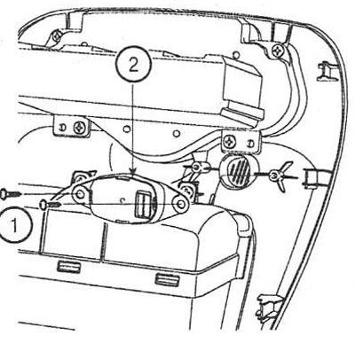
Installation
4. Installation is carried out in the reverse order of removal.
Examination
5. Turn on the ignition.
6. While supplying variable temperature air to the sensor inlet, measure the resistance between pins 2 and 4 of the sensor connector for each temperature value.
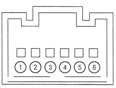
1. Pump (+); 2. "Mass" (-); 3. Humidity sensor signal; 4. Temperature sensor signal; 5. Nutrition (+); 6. Pump
| Temperature, C | Resistance, kOhm |
| 0 | 97,83±2,61% |
| 15 | 47,12±1,45% |
| 25 | 30,00 + 1,20% |
| 35 | 19,60±1,44% |
| 50 | 10,82±2,26% |
7. Using a diagnostic tester, measure the signal frequency between pins 2 and 3 of the sensor connector.
| Humidity, % | Signal frequency, Hz ±5% |
| 30 | 6976 |
| 40 | 6853 |
| 50 | 6728 |
| 60 | 6600 |
| 70 | 6468 |
| 80 | 6330 |
| 90 | 6186 |
| 100 | 6033 |