


Crankcase ventilation system diagram
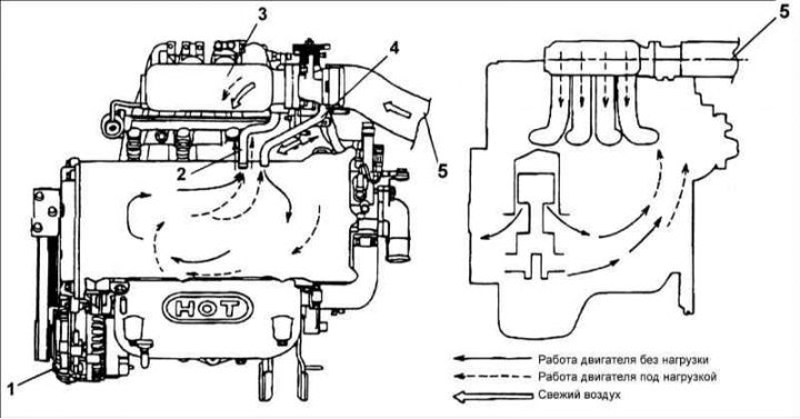
1 – generator; 2 – crankcase ventilation system valve; 3 – air chamber; 4 – wide hose; 5 – air intake pipe
The crankcase ventilation valve is controlled by the vacuum created in the intake manifold when the engine is running.
When the engine is running at idle speed, the valve is slightly open, resulting in a small amount of crankcase gases being diverted into the resonance chamber and subsequently burned in the engine cylinders.
As the engine speed increases, the degree of valve opening increases, resulting in an increase in the amount of crankcase gases that are diverted into the resonance chamber and subsequently burned in the engine cylinders.