
2. Using a scraper, clean the contact surface of the cylinder head from gasket residue.
3. Use compressed air to clean the bolt holes from soot and grease.
4. Using a scraper, clean the contact surface of the cylinder block of gasket residue.
5. Use a metal brush to clean the combustion chamber surfaces from carbon deposits.
6. Using a soft brush and solvent, thoroughly clean the cylinder head.
7. Use a scraper to remove carbon deposits from the valve heads. Using a wire brush, thoroughly clean the valves.
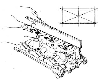
8. Using a ruler and feeler gauge, check the cylinder head for warpage by taking measurements in the directions shown in the figure. Standard non-flatness of the cylinder head contact surface: less than 0.03 mm, maximum permissible non-flatness value: 0.06 mm.
9. Check the combustion chambers, intake and exhaust ports, and contact surface for cracks. If cracks are found, replace the cylinder head.
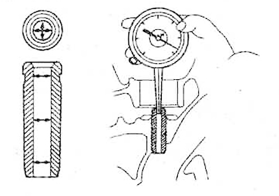
10. Using a bore gauge, measure the inside diameter of the valve guide bushings at the locations shown in the figure.
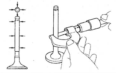
11. Using a micrometer, measure the diameter of the valve stem at the locations shown in the figure.
12. By subtracting the valve stem diameter at the corresponding point from the inner diameter of the guide bushing, determine the clearance between the guide bushing and the valve.
Nominal clearance between guide bushing and valve:
- Inlet: 0.020-0.050 mm;
- Graduation: 0.030-0.065 mm.
Maximum permissible clearance between the guide bushing and the valve:
- Inlet: 0.1 mm;
- Graduation: 0.13 mm.
If the clearance value exceeds the maximum permissible value, replace the valve and valve guide.
13. Measure the valve bevel angle. Check the degree of wear of the valve bevel and, if necessary, replace the valve with a new one.
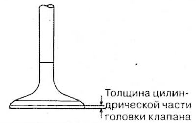
14. Measure the thickness of the valve head. Standard valve head thickness:
The original text is located on the portal HYUNDAIBOOK.RU
- Inlet: 1.0 mm;
- Outlet: 1.3 mm.
Maximum allowable thickness of valve head:
- Inlet: 0.5 mm;
- Outlet: 0.8 mm.
If the thickness of the cylindrical part of the valve head is less than the maximum permissible value, replace the valve with a new one.
15. Check the degree of wear of the valve stem, replace if necessary. -
16. Check the valve seat for signs of overheating. Check the tightness of the valve seat. Replace the valve seat if necessary.
17. Before boring the valve seat, check the degree of wear of the valve guide bushing. Replace the guide bushing if necessary. Boring of valve seats is performed on grinding machines, as well as using reamers. The dimensions of the valve seat must correspond to the nominal ones and ensure a tight fit of the valve.
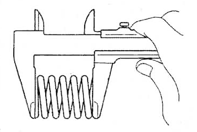
18. Using a square, check the deviation from the vertical of each valve spring. If the deviation from the vertical is more than 3°, replace the spring.
19. Check the length of the spring in a free state. Replace springs whose length does not correspond to the standard (42.5 mm).
20. Using a micrometer, measure the height of the intake and exhaust camshaft lobes. The standard value for the height of both the intake and exhaust valves is 43.95 - 44.15 mm. If the height of any of the lobes is less than the minimum limit, the camshaft must be replaced.
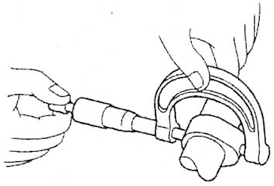
21. Use a micrometer to measure the diameters of the camshaft bearing journals. Nominal diameter of the camshaft bearing journals: 25.964 - 25.980 mm. If the diameter of the bearing journals does not correspond to the nominal, check the clearance between the bearing journals and the bearings.
22. Check the support bearings for delamination and wear. If damage to the bearing is detected, the bearing caps are replaced together with the cylinder head.
23. Check the clearance between the camshaft bearing journals and the bearings. To do this:
- 1) Clean the bearing caps and bearing journals.
- 2) Insert the camshaft into the cylinder head.
- 3) Place a calibrated plastic wire to measure clearances along the camshaft journal.
4) Install the bearing cover.
5) Remove the bearing cover.
6) Determine the clearance between the bearing shell and the camshaft journal by the width of the most flattened section of the wire using the scale on the wire packaging. If the clearance exceeds the maximum permissible value, replace the camshaft. If necessary, replace the bearing caps together with the cylinder head.
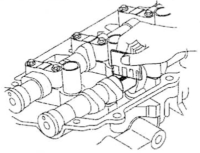
7) Remove the remaining calibrated wire.
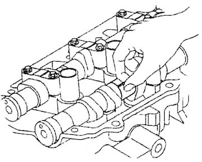
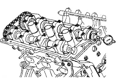
24. Install the dial indicator as shown in the figure. Measure the axial clearance of the camshaft by moving it back and forth along the cylinder head. The nominal value of the axial clearance is 0.1-0.15 mm. If the axial clearance exceeds the upper limit, replace the camshaft. If necessary, replace the bearing caps together with the cylinder head.
25. Remove the camshaft from the cylinder head.