Note:
- 1. To avoid incorrect connections during installation, mark all connectors and hoses when disconnecting them.
- 2. Check drive belts before removing the cylinder head.
- 3. Turn the crankshaft so that the piston of the first cylinder is at the top dead center of the compression stroke.
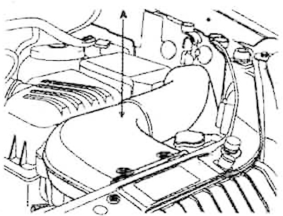
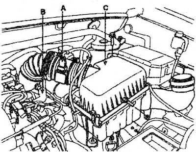
1. Remove the air intake (A).
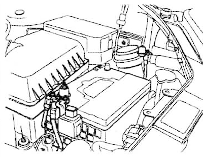
2. Disconnect the negative terminal from the battery.
3. Unscrew the radiator cap and the drain plug of the cooling system and drain the coolant.
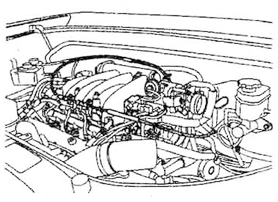
4. Remove the engine cover.
5. Disconnect the MAF sensor connector (A). Disconnect the breather hose (B) from the air cleaner hose. Remove the air cleaner (C) complete with the intake hose.
6. Remove the upper (A) and lower (B) radiator hoses.
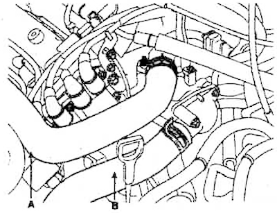
7. Remove the heater hoses (A).
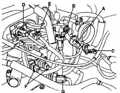
8. Disconnect the connectors on the cylinder head and intake manifold:
- 1. A - throttle position sensor connector;
- 2. B - idle speed control connector;
- 3. C-connector of solenoid valve;
- 4. D - VIS drive connector;
- 5. E - injector connector;
- 6. F - knock sensor connector;
- 7. G - camshaft position sensor connector;
- 8. A - coolant temperature sensor connector;
- 9. B- ignition coil connector:
- 10. C - crankshaft position sensor connector;
- 11. D - oxygen sensor connector;
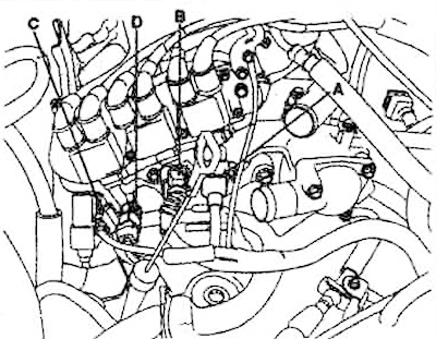
- 12.A - three fuel injector connectors.
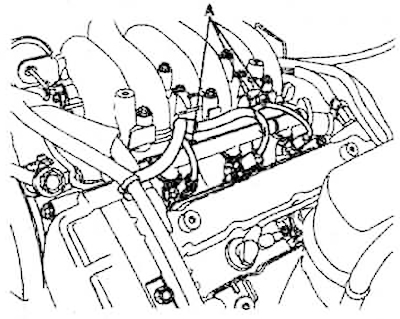
9. Disconnect the ground wire (A) from the hood cover.
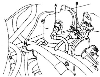
10. Disconnect the intake air temperature sensor connector (A) and the VIS actuator connector (B).
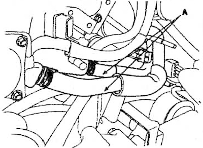
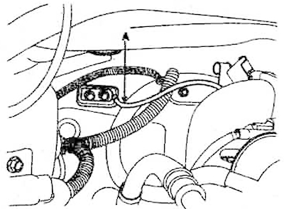
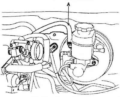
11. Disconnect the fuel hose (A) from the line.
12. Disconnect the crankcase ventilation hose.
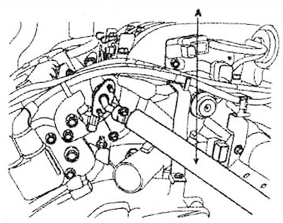
13. Disconnect the vacuum hose (A) from the brake booster.
14. Loosen the lock nuts and remove the throttle cable.
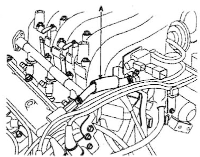
15. Remove the crankcase ventilation hose (A).
16. Remove the intake manifold.
17. Remove the power steering pump.
18. Remove the exhaust manifold.
19. Remove the drive belt.
20. Disconnect the high-voltage wires from the spark plugs.
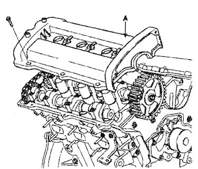
21. Remove the cylinder head covers (A).
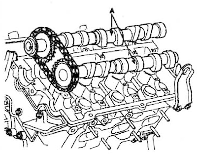
22. Remove the camshaft gears.
23. Remove the camshaft main bearing caps (A).
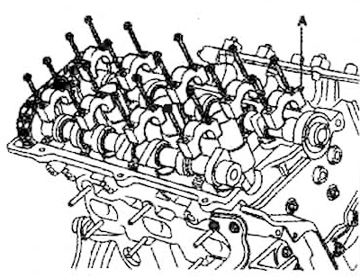 |
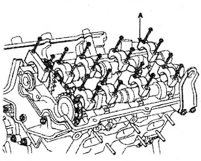 |
24. Remove the camshafts (A).
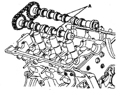 |
 |
25. Remove the rear drive belt cover (A).
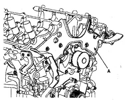
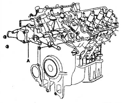
26. Remove the coolant temperature control unit (A) together with the water pump.
27. Uniformly loosen and then completely unscrew the 8 bolts securing both cylinder heads in several steps in the sequence shown in the figure. Remove these 16 bolts and the cylinder head gaskets.
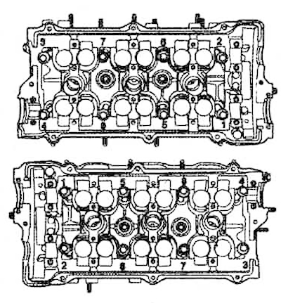
28. Remove the cylinder heads from the guide pins and place them on wooden blocks.