
Contents: Manifold Absolute Pressure (MAP)…⇓ Engine Intake Air Temperature (IAT)…⇓ Coolant Temperature (ECT) Sensor ⇓ Throttle Position Sensor (TP) ⇓ Camshaft Position (CMP) Sensor ⇓ Crankshaft Position Sensor (CKP) ⇓ Heated Oxygen Sensor (HO2S) ⇓
Manifold Absolute Pressure (MAP) Sensor
Location of fuel system components in a vehicle with 1.6 l and 1.8/2.0 l engines
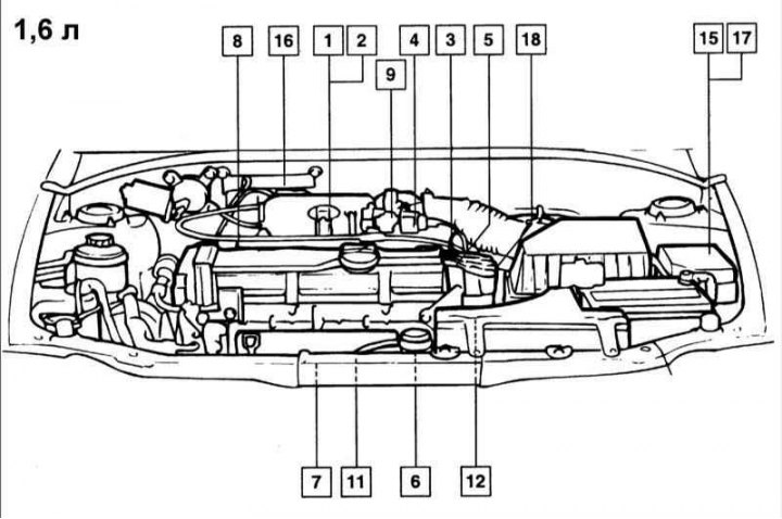
1 - manifold absolute pressure sensor (MAP); 2 - Intake air temperature sensor (IAT); 3 - coolant temperature sensor (ECT); 4 - Throttle Position Sensor (TPS); 5 - Camshaft Position Sensor (CMP); 6 - Crankshaft Position Sensor (CKP); 7 - heated oxygen sensor; 8 - injectors; 9 - Idle Speed Modulator (ISA); 10 - Vehicle Speed Sensor (VSS); 11 - knock sensor; 12 - Locking switch; 13 - ignition switch; 14 - ECM; 15 - air conditioning compressor relay; 16 - Fuel Evaporative System Solenoid Valve (PCSV); 17 - control relay; 18 - ignition coil; 19 - diagnostic connector
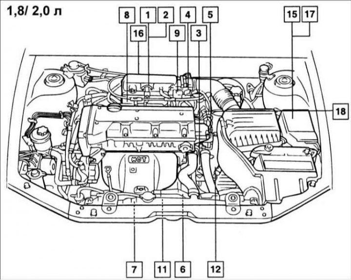
1 - manifold absolute pressure sensor (MAP); 2 - Intake air temperature sensor (IAT); 3 - coolant temperature sensor (ECT); 4 - Throttle Position Sensor (TPS); 5 - Camshaft Position Sensor (CMP); 6 - Crankshaft Position Sensor (CKP); 7 - heated oxygen sensor; 8 - injectors; 9 - Idle Speed Modulator (ISA); 10 - Vehicle Speed Sensor (VSS); 11 - knock sensor; 12 - Locking switch; 13 - ignition switch; 14 - ECM; 15 - air conditioning compressor relay; 16 - Fuel Evaporative System Solenoid Valve (PCSV); 17 - control relay; 18 - ignition coil; 19 - diagnostic connector
1 - manifold absolute pressure sensor (MAP); 2 - Intake air temperature sensor (IAT); 3 - coolant temperature sensor (ECT); 4 - Throttle Position Sensor (TPS); 5 - Camshaft Position Sensor (CMP); 6 - Crankshaft Position Sensor (CKP); 7 - heated oxygen sensor; 8 - injectors; 9 - Idle Speed Modulator (ISA); 10 - Vehicle Speed Sensor (VSS); 11 - knock sensor; 12 - Locking switch; 13 - ignition switch; 14 - ECM; 15 - air conditioning compressor relay; 16 - Fuel Evaporative System Solenoid Valve (PCSV); 17 - control relay; 18 - ignition coil; 19 - diagnostic connector
The manifold absolute pressure sensor is a sensitive variable resistor. It measures the pressure in the intake manifold, which changes depending on the engine operating conditions and is converted into voltage.
The sensor is also used to measure atmospheric pressure when starting the engine and provides engine operating modes at different altitudes above sea level. The sensor is powered by a voltage of 5 V. Based on the information from the sensor, the engine control unit regulates the amount of fuel supplied to the engine and also changes the ignition timing.
Examination
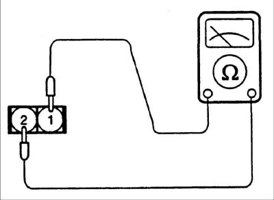
1. Connect a voltmeter between terminals 1 and 4 of the MAP sensor connector.
- Contact 1: "Mass"
- Pin 4: Positive Voltage
2. Measure the voltage.
- Output voltage with ignition on and engine not running: 4–5 V
- Output voltage at idle frequency: 0.5-2.0 V
3. If the sensor output voltage is different from the required one, replace the sensor.
Engine Intake Air Temperature (IAT) Sensor

The engine air temperature sensor is built into the absolute pressure sensor and is a thermistor whose resistance changes depending on temperature. The ECM takes into account the sensor signal and adjusts the pulse width supplied to the injectors, which changes the amount of fuel supplied to the engine cylinders.
Checking the sensor
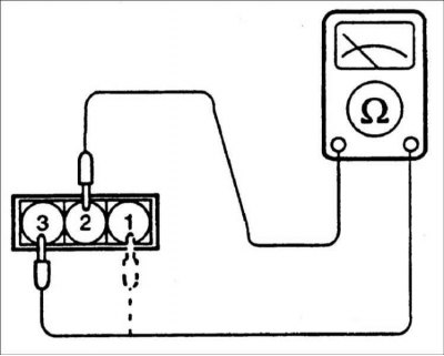
1. Measure the resistance between terminals 3 and 4 of the sensor connector.
Temperature | Resistance, kOhm |
0°C | 4,5–7,5 |
20°C | 2,0–3,0 |
40°C | 0,7–1,6 |
80°C | 0,2–0,4 |
2. If the sensor resistance differs from the required value, replace the sensor.
Coolant Temperature (ECT) Sensor
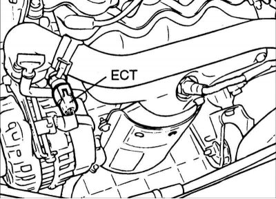
The coolant temperature sensor is installed in the cylinder head and monitors the coolant temperature and transmits a signal to the engine control unit ECM. The sensor uses a thermistor, which is sensitive to temperature changes. The electrical resistance of a thermistor decreases as the temperature increases.
When the engine is cold, the ECM operates in an open loop mode, resulting in a richer air/fuel mixture being supplied to the engine cylinders and an increased idle speed. This continues until the engine reaches normal operating temperature.
Examination
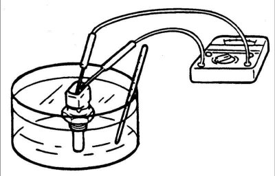
1. Remove the sensor from the intake manifold.
2. By heating a vessel with water and a sensor located in it, check its resistance.
Temperature | Resistance, kOhm |
–30°C | 22,22–31,78 |
–10°C | 8,16–10,74 |
0°C | 5,18–6,60 |
20°C | 2,27–2,73 |
40°C | 1,59–1,281 |
60°C | 0,538–0,650 |
80°C | 0,298–0,322 |
90°C | 0,219–0,243 |
3. If the sensor resistance differs from the required value, replace the sensor.
Installation
1. Apply LOCTITE 962T or equivalent to the sensor threads.
2. Screw in the sensor and tighten it to the torque specified in the specification. Tightening torque: 15–20 Nm.
3. Connect the connector to the sensor.
Throttle Position Sensor (TP)

The throttle position sensor is a variable resistor that rotates with the throttle shaft and provides information to the ECM to determine when the throttle is closed, fully open, or somewhere in between.
The sensor is rigidly connected to the throttle shaft. Depending on the position of the throttle valve, the resistance of the sensor changes.
Examination
1. Disconnect the connector from the throttle position sensor.
2. Measure the resistance between terminals 2 (ground) and 3 (power) of the sensor connector. Resistance: 0.7–3.0 kOhm.
3. Connect an ohmmeter to terminals 2 (ground) and 3 (sensor output) sensor connector.
4. Slowly open the throttle valve and make sure that the sensor resistance changes smoothly in proportion to the throttle valve opening.
The material is republished from the web portal www.HyundaiBook.ru
5. If the sensor resistance differs from the required value or changes abruptly, replace the sensor. Tightening torque: 1.5–2.5 Nm.
Camshaft Position (CMP) Sensor
The camshaft position sensor generates pulses at TDC of the piston of the first cylinder in the compression stroke, on the basis of which the ECM unit calculates the sequence of operation of the fuel injection system.
Crankshaft Position Sensor (CKP)
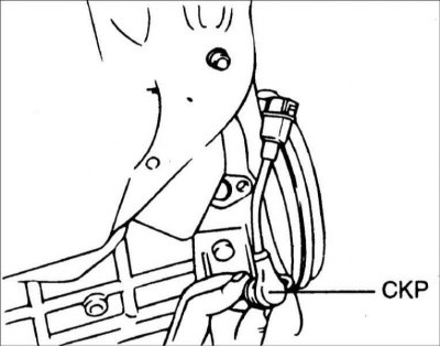
The crankshaft angle sensor consists of a magnet and a coil and is located near the flywheel ring gear. The sensor transmits information about the crankshaft rotation angle to the ECM (piston position). Based on the output signal information from this sensor, the ECM calculates the engine speed and crankshaft position.
Check (1.6L I4)
1. Disconnect the connector from the crankshaft angle sensor.
2. Measure the resistance between pins 1 and 2 of the sensor connector. Resistance: 0.486–0.594 kOhm at 20°C.
3. If the sensor resistance differs from the required value, replace the sensor. Gap between rotor and crankshaft angle sensor: 0.5–1.5 mm Tightening torque: 9–11 N·m.
Heated Oxygen Sensor (HO2S)
The heated oxygen sensor detects the oxygen concentration in the exhaust gases and converts it to a voltage, which it transmits to the ECM engine control unit.
The voltage at the sensor output is 500 mV if the fuel mixture is richer than theoretical and the voltage is 100 mV if the fuel mixture is leaner (higher concentration of oxygen in the exhaust gases). Based on this data, the engine control unit changes the fuel ratio in the fuel-air mixture.
Examination
- 1. Before checking, warm up the engine until the coolant temperature is 80–95°C.
- 2. Using an accurate digital voltmeter, measure the sensor output voltage.
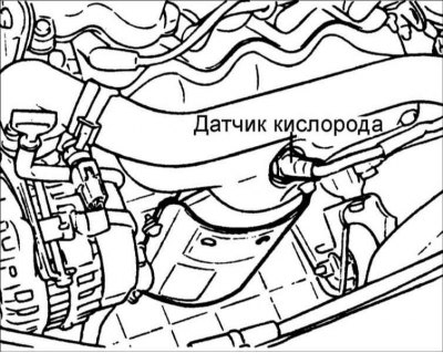
1. Disconnect the connector from the oxygen sensor and connect a voltmeter to the oxygen sensor connector.
2. While changing the engine crankshaft speed, measure the output voltage of the oxygen sensor. If the sensor output voltage is different from the required value, replace the sensor. Tightening torque: 50–60 Nm.